
Fig. 7. Schematic representation of an inverted micelle formed between adjacent IMM of a cristae.
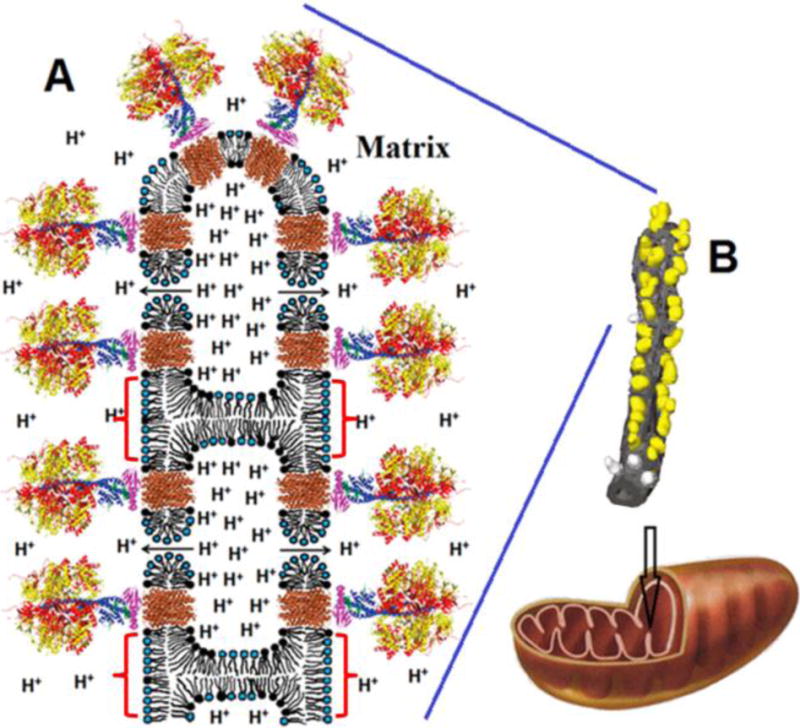
For simplicity, the inverted micelle includes only four ATP synthases and two toroidal like pores. We suggest that the formation of inverted micelles (shown by red brackets) and toroidal pores may be caused by the low pH when the H+ concentration is increased in IM space (see text for details). The release of protons from an inverted micelle to matrix occurs via F0 (shown in brown) and toroidal pores (shown by arrows). Toroidal pores are short-lived transient structures serving to release dangerously high H+ concentrations. The overall organization of ATP synthases (A) is based on the structure modified from Watt et al. 2010 [3]. The α- and β-subunits of catalytic domain are shown in red and yellow respectively. The subunits γ, δ, and ε of the central stalk are depicted in blue, purple, and green. The central stalk and the C-ring (given in brown) together constitute the rotor. Phospholipids with the polar heads (black) represent CL. Phospholipids with blue polar heads represent the other acidic and neutral phospholipids. The image of tubular cristae of mitochondrion (B) showing F1 head dimers on its surface was modified from Strauss et al. 2008 [4]. The F1 heads are yellow and the membrane is grey. The F1 heads not assigned to dimers are shown in lighter grey.