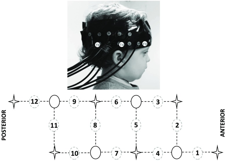
Fig. 2.
The fNIRS headgear and channel layout. An infant wearing the headgear with the location of the 10 to 20 coordinates F8, T4, and T6 overlaying the photo. T4 was located at the midpoint of the lower row of channels (the source optode between channel 4 and 7; upper panel). The array design showing the location of the channels (dashed circle), sources (star), and detectors (full circle; lower panel).

