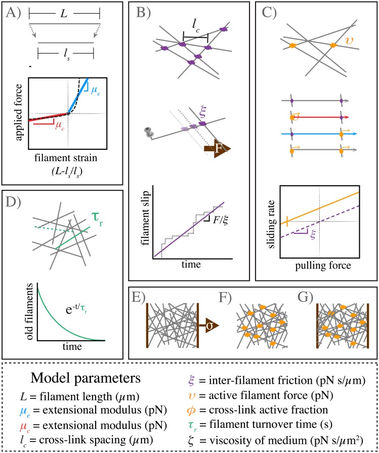
Fig 1. Schematic overview of modeling framework and assumptions.
A) Filaments are oriented linear springs that are stiffer in extension than in compression. B) Cross-linking occurs at all filament crossings; we represent cross link resistance as an effective drag, proportional to the relative velocity of the overlapping filaments. C) We represent motor activity as a linear force-velocity relationship with a fixed force at zero velocity directed towards a filament’s pointed (-) end. We implement spatial heterogeneity by imposing motor activity at a fixed fraction of filament crossover points, resulting in variation in the magnitudes of compressive vs extensile vs translational forces along individual filament segments. D) Whole filaments disappear at a constant rate; new filaments appear with random positions and orientations at the constant rate per unit area, such that entire network refreshes on a characteristic timescale τr. E-G) Three different simulation scenarios: E) Passive response to uniaxial stress, F) Free contraction of an active network and G) Isometric contraction against a fixed boundary.

