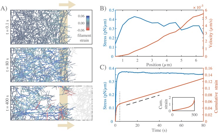
Fig 2. Networks with passive cross-links and no filament turnover undergo three stages of deformation in response to an extensional stress.
A) Three successive time points from a simulation of a 6.6 × 4 μm network deforming under an applied stress of 0.5 pN/μm. Stress (tan arrows) is applied to filaments in the region indicated by the tan bar. In this and all subsequent figures, filaments are color-coded with respect to state of strain (blue = tension, red = compression). Network parameters: L = 1 μm, lc = 0.3 μm, ξ = 10 nN ⋅ s/μm. B) Mean filament stress and velocity profiles for the network in (A) at t = 88s. Note that the stress is nearly constant and the velocity is nearly linear as predicted for a viscous fluid under extension. C) Plots of the mean stress and cumulative network strain vs time for the simulation in (B), illustrating the three stages of deformation: (i) A fast initial deformation accompanies rapid buildup of internal network stress; (ii) after a characteristic time τc (indicated by vertical dotted line) the network deforms at a constant rate, i.e. with a constant effective viscosity, ηc, given by the slope of the dashed line; (iii) at long times, decrease in filament density, and loss of network connectivity, leads to material failure (see inset).

