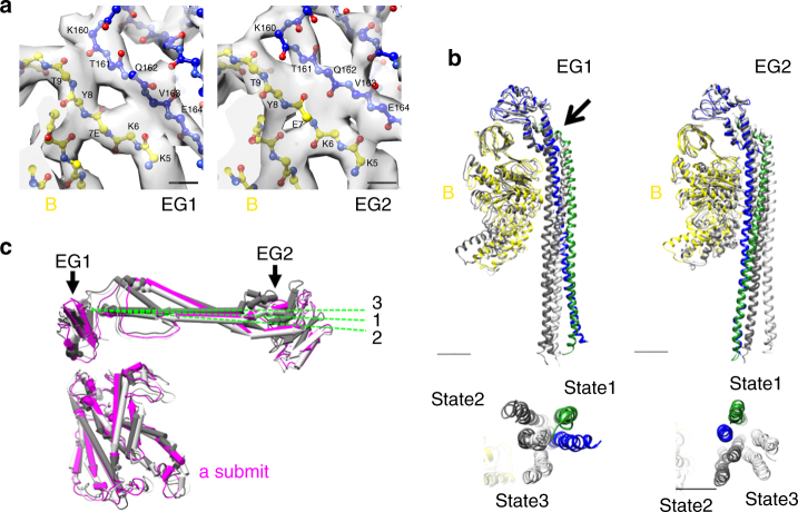
Fig. 3.
Structure of the peripheral stator subunits. a Close-up views of the interaction surface of B- and E-subunits in state1. Residues are depicted in sticks format and experimental maps are shown in semi-transparent gray. Scale bar, =3 Å. b Circular motions of EG1 and EG2 during transition of three rotational states. The E-subunit in state1 is colored blue, and the G-subunit is colored green. E- and G-subunits in state2 are shown in dark gray, and those in state3 are shown in light gray. These subunits are superimposed at the N-terminal β-barrel domain of the corresponding B-subunit. The arrow indicates the pivot point of the right handed coiled-coil of the EG1. The lower panels are bottom views of the N-terminal region of the EG-subunits. Scale bar, 20 Å. c Comparison of the N-terminal domain of a-subunit in three states. Subunits are superimposed at the C-terminal domain of the a-subunit. These subunits in state1–3 are colored in magenta, dark gray, and light gray, respectively

