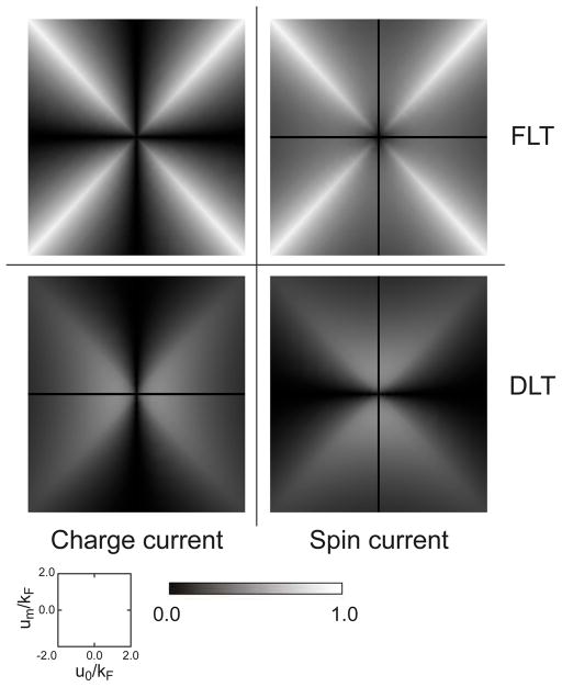
FIG. 6.
Magnitude of spin-orbit torque in the presence of interface magnetism. We plot spin-orbit torque as a function of u0/kF and um/kF. To compare magnitude clearly, we plot absolute values, discarding the signs. The upper two panels represent fieldlike components [Eq. (24a)] and the lower two panels represent damping-like components [Eq. (24b)]. The left two panels represent charge-current-induced contributions (proportional to ). The right two panels represent spin-current-induced contributions (proportional to ). The values are divided by hRħeExA/24πmekF for all panels, and additionally divided by for the charge-current-induced contributions (+ for FLT and −for DLT) and for the spin-current-induced contributions. The resulting values are dimensionless. The black lines near u0 = 0 or um = 0 are regions where spin-orbit torque is not computed due to numerical instability.

