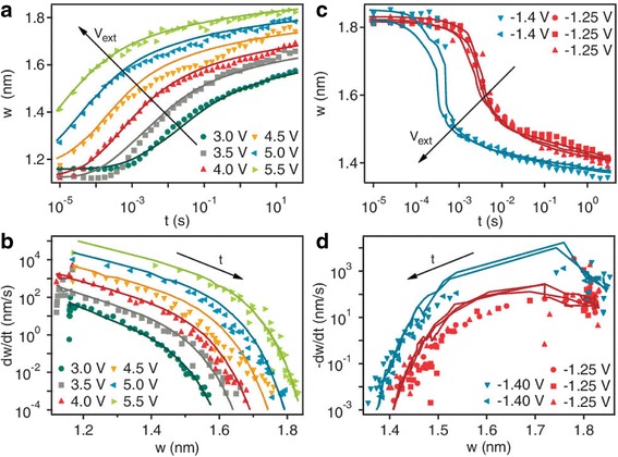
Fig. 6.

Dynamical behavior of the tunnel barrier width w. The evolution of the state variable w occurs as a function of time for different applied voltages for a series of a off-switching and c on-switching state tests on the same device. Legends indicate the applied external voltage. The lines are the numerical solution to the respective switching differential equations described in the text. b, d The numerical derivative w˙ of the data in a and c plotted as a function of w for the different applied voltages. The lines are calculated from the differential equations using the measured values of w and i at each point in time. The irregularity of the calculated w˙ vs w lines in the on-switching plots is caused by the changes in the current that accompany the change in state (w˙ is a function of two variables, w and i, and both are changing). The derivative of the state variable w˙ can be interpreted as the speed of the oxygen vacancy front. This is because the applied voltage pushes it away from or attracts it toward the top electrode [70]
