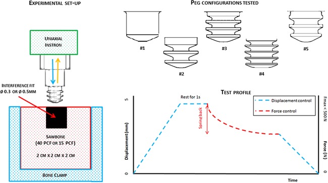
Figure 1.

Left: Experimental set‐up for pull‐out tests—a peg specimen is mounted into a uniaxial Instron and pushed into a 2 × 2 × 2 cm3 clamped Sawbone block (40 or 15 PCF) with a 0.3 or 0.5 mm diametral interference fit. Top right: The five peg geometries tested. Bottom right: Test profile for the push‐in/pull‐out test which was split into three parts: push‐in of the peg in displacement control, measurement of spring‐back in force control and pull‐out in displacement control.
