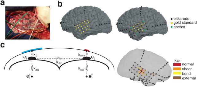
Figure 3.

Localization Algorithm. (a) Intra‐operative photographs were used to visually identify electrode locations. (b) Identified electrodes are manually placed on the cortical envelope (left); a subset of these are used as anchor points (right), while the rest are used as the gold standard locations to validate the localization algorithm. (c) Final electrode localization is optimized based on a spring model (left). Springs governing the energy of displacement (k disp) are placed between the final (ei) location and CT‐registered location ( ), between the final electrode location and the cortical surface (k fit) or anchor point (k anch), and between neighboring electrodes (k def). Neighboring electrodes (right) were chosen to model normal, bend, and shear forces, and external connections were made between hardware within 15 mm [Color figure can be viewed at http://wileyonlinelibrary.com]
