
Fig. 2.
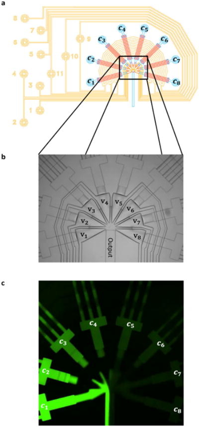
a) Design of a Signal Generator Module; control lines in yellow, flow lines in blue and red. Solenoid controlled pressure is connected to the control lines (yellow circles numbered 1-11). The input reservoirs are pressurized and connected to the blue circles. Valves 9-11 cross all inputs in a circular manner to achieve equal flow rates of all inputs by peristaltic movement.1 Valves 1-8 control each input individually and allow to choose desired concentrations at the junction. b) Bright field image of the injector junction with triangular converging valves v1 – v8. c) Snapshot from movie (Electronic Supplementary Information) of the operating signal generator, mixing fluorescent dye solutions of different concentration c1 – c8.