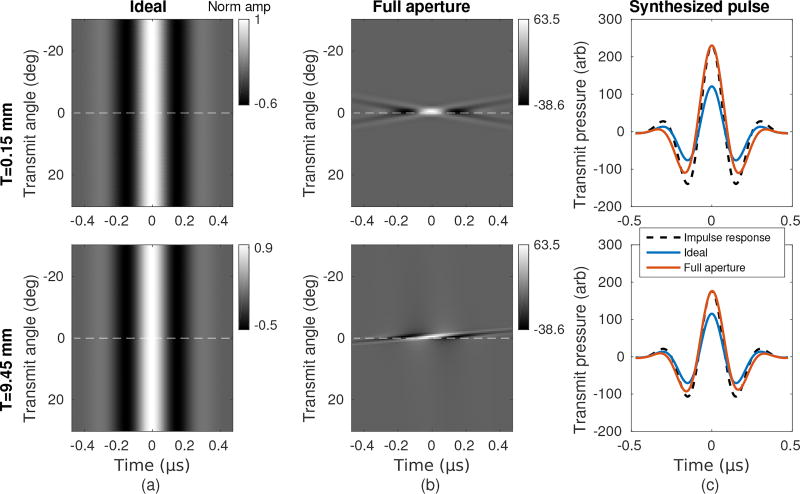
Fig. 3.
Simulated transmit pressure field results for a receiver at (x, z) = (0, 40mm). All results were scaled by the same normalization factor. (a) “Ideal” extracted pulses corresponding to emission from only the desired transmit element. The angle of the receiver relative to the array is denoted by the dashed white line. (b) Actual extracted pulses using the full aperture in a focused transmit configuration. (c) Pulses were synthesized by summing across transmit angles. The transducer impulse response is included for reference and scaled to match the full aperture pulse amplitude.

