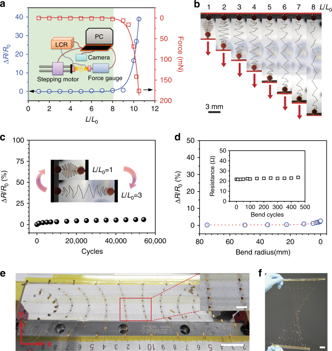
Fig. 2.
Mechanical and electrical testing of the meandering interconnects. a Relative resistance and tensile force change with the extension of the meandering interconnects (50-μm-wide, 50-μm-thick polyimide wire coated with Ag thin films); the green section shows a perfectly stable performance region, and the inset depicts a schematic of the customized stretch-testing platform. b Optical images of a meandering wire stretched from an L/L0 of 1 to 8 (scale bar: 3 mm). c Durability testing at 300% expansion, with an inset showing the stretching at L/L0 = 1 and L/L0 = 3. d Relative resistance change vs. bend radius, with an inset showing bend durability at a bend radius of 150 μm. e Optical image of an expanding SCMN (scale bar: 2 cm), with an inset depicting an enlarged view of the red rectangle (scale bar: 5 mm). The network is made of 100 nodes (1.6 mm in diameter) connected by 50-μm-wide, 25-μm-thick polyimide wires coated with Au thin films. f Optical image of a twisted SCMN (scale bar: 2 cm)

