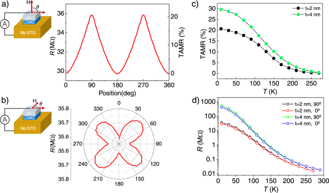
Figure 5.
(a) Resistance and TAMR vs. θ (position of the sample) with the field rotating from OOP, θ = 0,180° to IP θ = 90,270°. (b) Resistance vs. rotation of the sample with the field applied IP. Both measurements were taken at 9 T, 10 K and V of 900 mV. Measurement configurations on the left. (c) TAMR vs. temperature (calculated from resistance vs. rotation curves) and (d) resistance vs. temperature of 2 nm and 4 nm-thick barrier samples with magnetic field applied OOP (red, blue) and IP (black, green).

