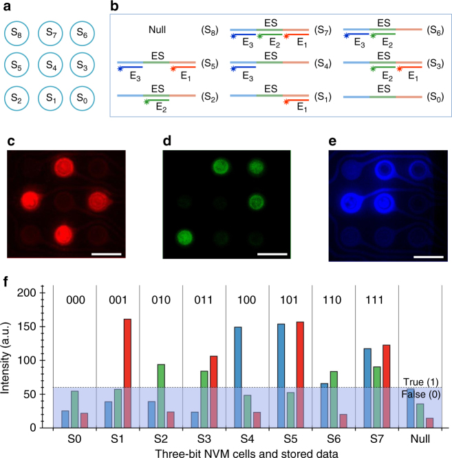
Fig. 3.
A DNA multi-cell TLC-NVM system. a The addresses of an array of eight individually addressable three-bit memory cells and a null cell (S0–S8). b Possible combinations of the three encoding bits. c–e Status of the E1 (c), E2 (d), and E3 (e) bits on the eight memory cells and the null cell. f Fluorescence intensity and written data of the eight memory cells. S0–S8: cell 1 to cell 9. ES: encoding sequence with three non-overlapping DNA segments, one for each of the three bits (LSB, SSB, and MSB). E1: Cy3-labeled DNA probe to encode LSB. E2: FAM-labeled probe to encode SSB. E3: Cy5-labeled probe to encode MSB. Scale bars are 160 µm

