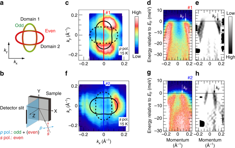
Fig. 1.
Electronic structure of the twinned FeSe at 15 K in the orbital ordered state. a Schematic FSs at the zone center. x and y are coordinates along the crystal axes of the orthorhombic setting. Due to the orbital ordering, two elliptical FSs are overlapped. Portions of the orbital contributions in those FSs are indicated by red and green for even and odd parity with respect to the mirror plane defined in b, respectively. b Experimental configuration. A mirror plane is defined to be parallel to the detector slit. Definition of p- and s-polarized light and sample axes is shown. c Plots of the ARPES intensity at EF as a function of the two-dimensional wavevector measured with p-polarized light. The intensity is obtained by integrating the spectra within ±3 meV with respect to EF. The experimental FS (solid ellipse) and a duplicate rotated by 90° caused by twin domains (dashed ellipse) are shown. d ARPES intensity plot, e momentum second derivative of d at #1 in c. The arrow indicates a kF position. f–h The same as c–e but taken with s-polarized light reflecting the other domain

