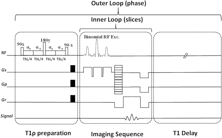
Figure 6.
The imaging sequence timing diagram consists of T1ρ preparation, 3D turbo-Flash readout, and T1 recovery delay. To compensate the effect of B1 inhomogeneities, the spin-lock pulse (SL) was divided into four segments with alternative phase. A 180° refocusing pulse was applied between two pairs for B0 inhomogeneity compensation. One phase line from all slices was acquired after applying the preparation module (inner loop). After T1 restoration delay the preparation module was applied again to acquire another phase line (outer loop).

