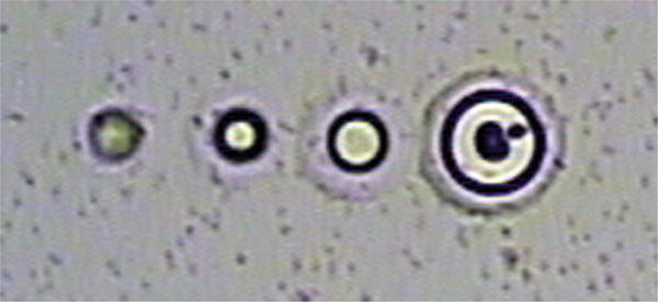
Fig. 2.

Ideal infrared (IR) laser melt spots. A series of spots generated with the IR laser are shown. The blurred spot on the far left indicates insufficient heating to melt the thermoplastic membrane to create a genuine melt spot. The membrane remains suspended above the sample. The next spot is small, but would work well for capturing minute samples of just one or a few cells. The third spot is generally ideal for excellent attachment of the thermoplastic membrane to the sample tissue. The far right spot is quite large, but could be effective for collecting large samples, where maximal contact is useful.
