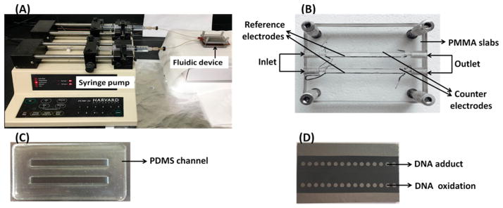
Scheme 2. Photographs of Fluidic Array Featuring Two PDMS Channels in a PMMA Housing∇.
∇ Ag/AgCl reference and Pt counter wire electrodes are symmetrically placed along the lengths of the channels. (A) Fluidic reactor shown with dual syringe pump to deliver buffer and reactants solutions to the array. (B) Fluidic reactor showing channels and auxiliary electrodes. (C) PDMS slab showing two fluidic channels. (D) Pyrolytic graphite (PG) chip showing array of two rows of microwells.

