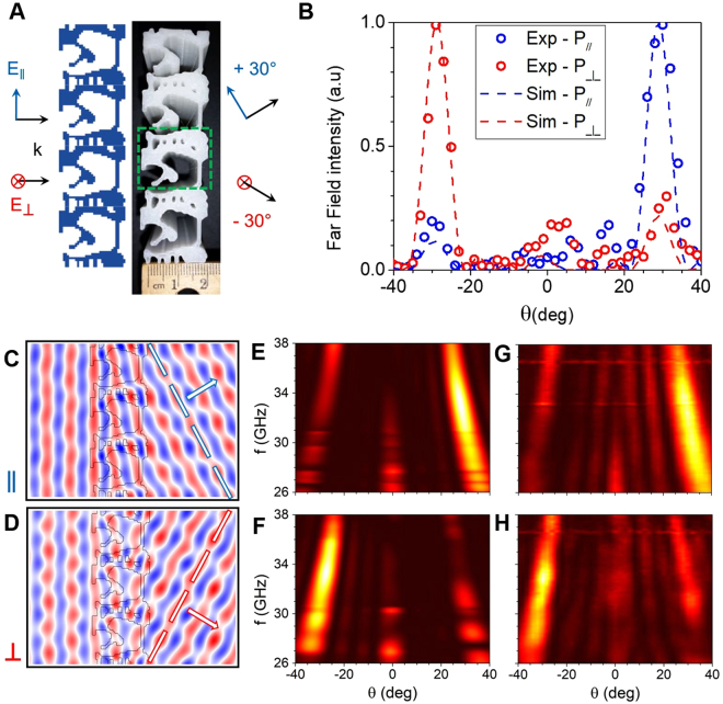
Figure 2.
Inverse-designed polarization splitter. (A) Schematic drawing (left) and top-view photograph (right) of the 3D-printed 30° polarization splitter. The green rectangle indicates the unit cell of the grating. (B) Simulated (dashed lines) and measured (circles) far-field power as a function of deflection angle for both parallel and perpendicular polarizations. (C) and (D) Simulated Hz and Ez field amplitudes for parallel (C) and perpendicular (D) polarizations, respectively, at 33 GHz. (E) to (H) Simulated (E,F) and measured (G, H) far-field intensity profiles as a function of the output angle and the millimeter-wave frequency for parallel (E,G) and perpendicular (F,H) polarizations.

