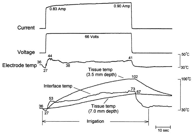
Fig. 8.
Figure 10 from Nakagawa et al [5] demonstrating an irrigated RF application using parameters almost identical to those used in Figure 7 (Group 6). Note that, despite continued (constant) RF application, there are sudden downward deflections in both “interface temp” and electrode temp (arrow), followed by a more gradual rise. The electrode temperature pattern is virtually identical to that in Figure 7. The interfacial temperature pattern is similar in pattern to but different in scale from that in Figure 7. No impedance tracing was supplied with this figure. Reproduced with permission.

