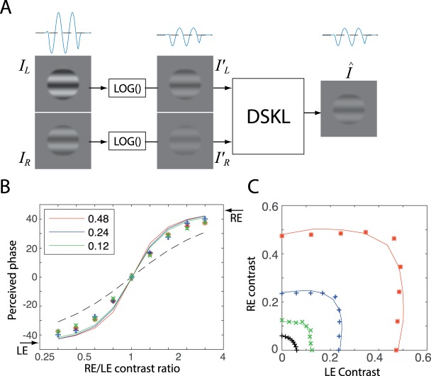
Figure 8.
Model simulation: Binocular combination of first-order sinewave gratings. The best-fit model parameters of Figures 3 and 4 (Table 4) were used in the simulation. (A) Two input sinewave gratings, their compressed images by a luminance compressor (logarithmic luminance function), and the binocular output of the DSKL model. The one-dimensional sine waves are also shown for the LE input, its compressed image and the binocular output. (B) Simulation of binocular phase combination. The two eye's input phases are −45° and 45°, respectively as indicated by arrows on the sides, and the base contrast is 0.48 (red), 0.24 (blue), or 0.12 (green). The dashed black curve represents the prediction of the linear summation model. (C) Simulation of binocular contrast combination: equal contrast contours. The two eye input phases are identical and the reference contrast is 0.48 (red), 0.24 (blue), 0.12 (green), or 0.06 (black). Experimental data from Ding and Levi (2016) are indicated as colored markers.

