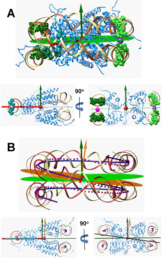
Figure 1.

(A) Definition of the NCP-centred coordinate system. The top cartoon shows how the atomic 1KX5 structure was used to define COM (red sphere), symmetry axis (red stick), NCP plane (green plane) with the green vector showing the normal to the NCP plane. Lower left and right cartoon are slices through the NCP structure explaining the details of the definition of the coordinate system. Atoms of the DNA used to create coordinates are shown as spheres: coloured cyan is the central “0” b.p that defines symmetry axis; atoms in light and dark green are used to build the NCP plane. (B) Comparison of the suggested NCP-centred coordinate system and the coordinate system based on the DNA symmetry approximated as superhelix (SH). The top cartoon presents a general view, lower left and right drawings illustrate details. The Curves+ program90 was used to build the sequence of the DNA double helix shown as magenta points at the level of each DNA bp. The dark blue line shows the ideal superhelix (SH) structure fitted to the 129 central points of the dsDNA axis. The magenta sphere shows the centre of the SH; the yellow-orange plane and the vector are respectively the SH axis and plane drawn thought the SH centre normal to the SH axis; the light cyan stick is the dyad axis of the SH. NCP symmetry axes and plane as in (A).
