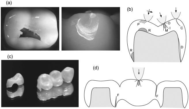
Figure 1.
Failure modes in ceramic prostheses from tensile stresses at the occlusal surface and cementation interface. (a) Images of failure in laboratory tests on crowns, splitting (left) and chipping (right), and (b) corresponding schematic diagram depicting various individual fracture modes: full cone cracks outside (O) and within (I) the contact zone; median cracks (M) beneath contact; partial cone cracks (P) from sliding; chipping cracks (C) adjacent to the side wall; flexure radial cracks (R) at the cementation surface, either below the contact or at the margins; delamination cracks (D) at the cementation/substrate interface. (c, d) Corresponding image and schematic diagram for fixed dental prosthesis, indicating dominant flexure cracks (F) at connector sites. Arrows indicate occlusal loading. Modified from Zhang et al. (2013).

