Figure 3.

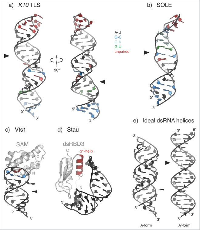
Recognition of structured localization signals. (a-b) Solution structures of the Transport and Localization Signal from K10 mRNA (K10 TLS; a) (PDB 2KE633) and of the SOLE hairpin from osk mRNA (b) (PDB 5A1770). A-U base pairs are shown in black; G-C base pairs in blue; G:A base pairs in cyan; G:U base pairs in green; unpaired residues (loops and bulges) are highlighted in red. Both stem-loops present widened major grooves (indicated by broad arrowheads) as compared with the common A-form of dsRNA helices (e). (c) Solution structure of yeast Vts1 Sterile α motif (SAM) bound to the Smg Recognition Element (SRE) (PDB 2ESE58). The loop residues forming a base pair are colored in blue; the specifically recognized G residue at position 3 of the loop is highlighted in red. The position of the major groove is indicated by an arrowhead. In the case of SRE RNA, the major groove has an intermediate width between that of the K10 TLS and that of an ideal A-form dsRNA and it is not involved in Smg/Vts1 recognition.54 (d) Solution structure of the third dsRNA-binding domain (dsRBD3) of Drosophila Stau bound to an artificial stem-loop sequence (PDB 1EKZ68). The N-terminal α-helix (α1-helix), which is potentially involved in sequence-specific contacts with the RNA loop, is highlighted in red. (e) Cartoon representation of ideal dsRNA structures (generated in Coot129), assuming the canonical A-form (left) or the unusual A'-form conformation (right), which is reminiscent of the B-form of dsDNA. Major grooves are indicated by arrowheads (thin for A- and broad for A'-form, respectively).
