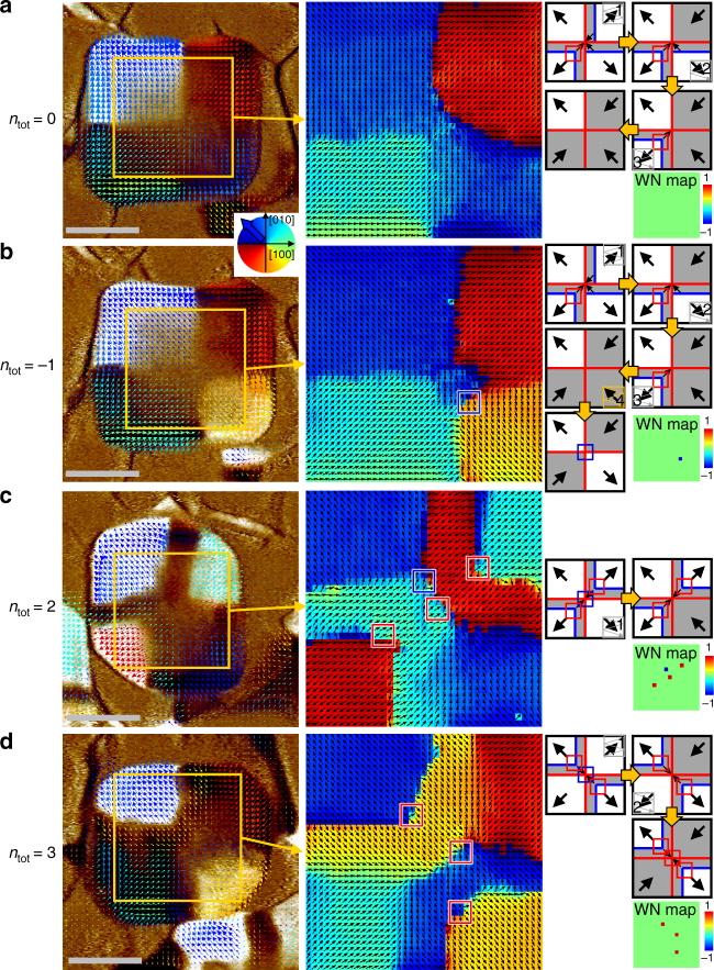
Fig. 7.
Reconfiguration of the total winding number of BFO nanoplates by selectively switching quadrant ferroelectric domains. Electrically controlled domain configurations show various total winding numbers, such as a ntot = 0, b ntot = − 1, c ntot = 2, and d ntot = 3. Left: Vector maps of IP piezoresponse overlaid on the corresponding OOP PFM contrast; (middle) IP piezoresponse angle maps extracted from the yellow boxes; (right) Simplified schematics describing the domain switching sequence with expected vortex (red box) and/or antivortex (blue box) points; winding number maps were determined experimentally. The dark grey background regions have downward polarisations in contrast to the as-grown white regions with upward polarisations as a result of non-local ferroelectric switching of selected quadrant domains. It is noteworthy that the case of ntot = 2 includes the creation of an unintended vortex–antivortex pair, but the measured total winding number is the same as the expected one that contains the two topologically protected vortices. Scale bars represent 200 nm

