Fig. 8.
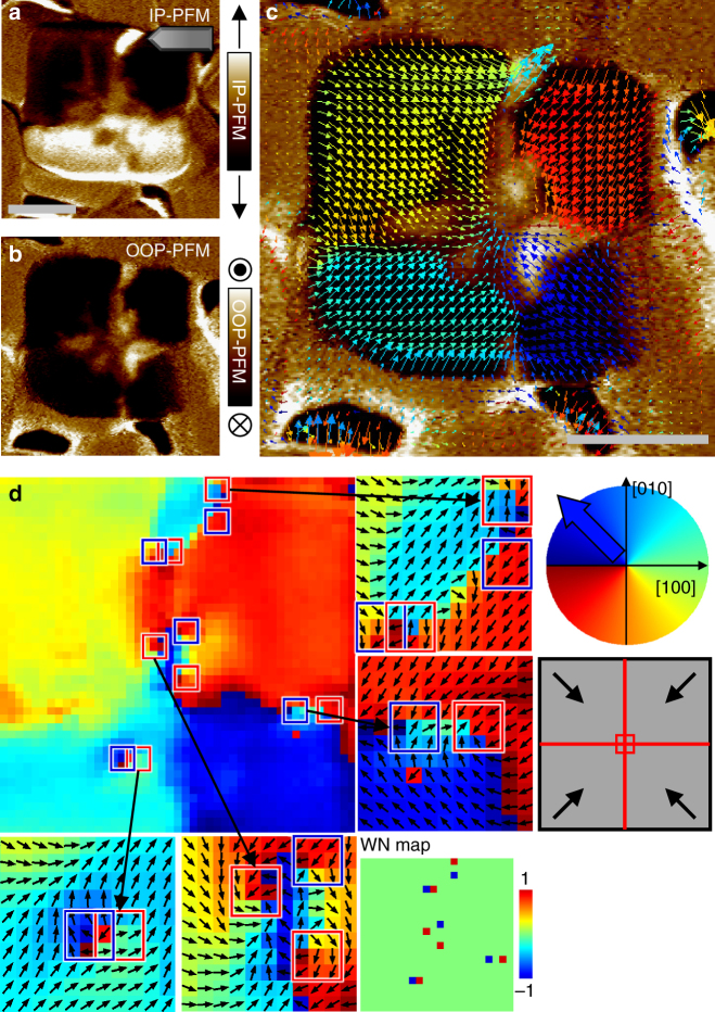
An excited state due to the creation of multiple vortex and antivortex pairs. a, b IP and OOP PFM images measured after electrical poling on the entire top surface of the plate with the type 2 state (the same plate in Fig. 3) by a dc biased tip at +3 V. The OOP polarisations in most areas were switched to downward polarisations (detected as dark contrast in the OOP PFM image) and flipped to inward IP polarisations. The same polarity of the polarisation merging at the central region produced a complex domain structure of relatively weak polarisation-up piezoresponses to partially avoid a strongly charged domain wall and reduce electrostatic energy. c IP piezoresponse vector map overlaid on OOP PFM contrast. d The corresponding colour map of IP piezoresponse directional angle. Vortex–antivortex pair generations are observed near polarisation-up regions. The central region contains one more vortex inevitable for this structural geometry, as explained in the schematic, thereby leading to a total winding number of 1. The electric frustration at the central region leads to the generation of various competing states and the strong electric perturbation during the whole-area poling offers more chances for excited states with multiple pairs of the particle and its anti-particle in the ferroelectric nanostructures subject to a strain gradient. Scale bars represent 200 nm

