Abstract
We describe a new series pneumatic artificial muscle (sPAM) and its application as an actuator for a soft continuum robot. The robot consists of three sPAMs arranged radially round a tubular pneumatic backbone. Analogous to tendons, the sPAMs exert a tension force on the robot’s pneumatic backbone, causing bending that is approximately constant curvature. Unlike a traditional tendon driven continuum robot, the robot is entirely soft and contains no hard components, making it safer for human interaction. Models of both the sPAM and soft continuum robot kinematics are presented and experimentally verified. We found a mean position accuracy of 5.5 cm for predicting the end-effector position of a 42 cm long robot with the kinematic model. Finally, closed-loop control is demonstrated using an eye-in-hand visual servo control law which provides a simple interface for operation by a human. The soft continuum robot with closed-loop control was found to have a step-response rise time and settling time of less than two seconds.
I. INTRODUCTION
Soft robots are characterized by their continuously deformable structures that are compliant and can withstand large deformations during normal operation [1]. Though their flexibility and compliance make precise, high bandwidth control more challenging than their rigid counterparts, soft robots have desirable properties such as conformability to their environment ingrained in their mechanical structures. Because of this, soft robots are increasingly being developed for use in cluttered and unstructured environments such as search and rescue operations [2], manipulation [3], [4], and human-centered tasks [5], [6].
Soft robots require complementary actuation that is soft and light. Because pneumatic artificial muscles (PAMs) are usually soft reinforced membranes that both bulge and contract when inflated with compressed gas [7], they are a natural actuation choice for soft robots [8]. Different PAM variants have been developed, including McKibben Muscles [9], pouch motors [10], pleated PAMs [7], and inverse PAMs [11], all of which are contractile actuators that transform the energy of compressed gas into mechanical work [12].
Like soft robots, continuum robots are flexible, and therefore have the potential for greater conformability to the environment than rigid robots [13]. However, many continuum robot designs have not been soft. These include the tendon-driven manipulators of Camarillo et al. [14] and Gravagne and Walker [15], which use hard end-plates to route the cables. Pneumatically actuated continuum robots such as the Slime Robot [16] and the Bionic Handling Assistant [17] have also included hard components such as shells, springs, and cables. Examples of soft continuum robots include the fluidic elastomer driven robot by Marchese et al. [18], the Stiff-Flop arm [19], the octopus inspired arm of Laschi et al. [20], and the hybrid pneumatic-tendon actuated arm of Stilli et al. [21].
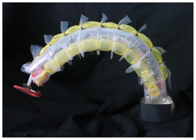
To create an entirely soft robot arm, we introduce a new series pneumatic artificial muscle (sPAM) that is capable of actuating such a soft robot. Inspired by pouch motors [10], the sPAM consists of multiple PAMs in series (Fig. 2) and are easily fabricated from thin sheets of polyethylene that require no casting or molding. Unlike pouch motors, sPAMs are axisymmetric and as a result, have a larger stroke than pouch motors, particularly in the thin aspect ratios that are necessary for continuum robot actuation. As seen in Fig. 1, our continuum robot is made almost entirely from low-density, thin-walled polyethylene tubing and has no hard components aside from a miniature camera at its end. Because of this, the robot has lower inertia and is therefore safer. The robot body is also simple to construct from low cost and readily available materials and requires no casting or molding.
Fig. 2.
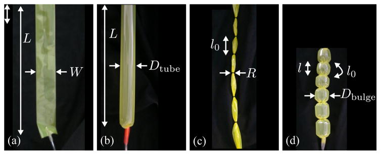
Thin-walled polyethylene tubing (a) deflated and (b) inflated. An sPAM is a length of polyethylene tubing with o-rings spaced at regular intervals (c) deflated and (d) inflated. l0 is unchanged during inflation.
Fig. 1.
Soft continuum robot with series pneumatic artificial muscles (sPAMs) attached.
This paper first describes the design and fabrication of the sPAM actuator and robot body. Next we develop a model for the sPAM actuator that describes both its contraction and force-displacement behavior. Building on the sPAM actuator model, we develop a kinematic model for the soft continuum robot. We conclude with a demonstration of control of the robot using an eye-in-hand visual servo control law and use it for a pick-and-place task. Such a robot has potential for use in manipulation tasks of light-weight objects in environments where safety is a concern.
II. Design and Fabrication
The soft continuum robot presented in this paper has a body that is unique in that its ease of construction from low cost, off-the-shelf materials. We describe the design of sPAMs, the continuum robot body that uses the sPAMs as actuators, and of the peripheral components used to control the robot in this work. These include electronic regulators, and vision system. Less expensive peripherals may be used in hobby applications.
A. sPAM Design
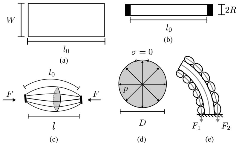
A sPAM is made from a thin rectangular sheet of polyethylene tube that is sealed (heat bonded) on one end so that it inflates. When deflated, the sheet is W wide by L long and has a wall thickness of t (Fig. 2(a)). The length and width are design parameters whose effects are explored in Section III-A. When inflated, the polyethylene tubing becomes cylindrical in shape with length L and diameter Dtube = 2W/π (Fig. 2(b)). In our construction, L = 42 cm, W = 3.8 cm and t = 0.051 mm.
Rubber o-rings (4.46 mm OD) spaced at regular intervals along the length of the sPAM (3.5 cm in this work) cause the profile of each actuator segment to become bulged when compared to its deflated state (Fig. 2(c)). Assuming the material does not stretch a significant amount, the actuator will contract when inflated (i.e. its length will be reduced), due to its bulged profile (Fig. 2(d)).
B. Robot Design and Fabrication
The continuum robot is composed of a pneumatic backbone and three actuators arranged radially around the backbone (Fig. 1). As explained in Section III-B, the pneumatic backbone may be thought of as a cantilevered beam whose stiffness is derived from its internal pressure. Similar to a tendon-driven continuum manipulator [14], the sPAMs exert moments on the pneumatic backbone to cause bending of the robot.
Each sPAM is attached to the pneumatic backbone by first heat bonding a strip of polyethylene to the side of the pneumatic backbone at regular intervals to match the spacing of the rubber o-rings. The polyethylene strips are then cut in regular intervals between the heat seals and a hole is punched through each newly created tab. The deflated sPAM is then threaded through the holes and plastic tubing is sealed inside the open end of the sPAM. Once all three sPAMs are attached, a final length of tubing is sealed inside the pneumatic backbone and the loose ends are run to the pneumatic system explained below.
C. Pneumatic System
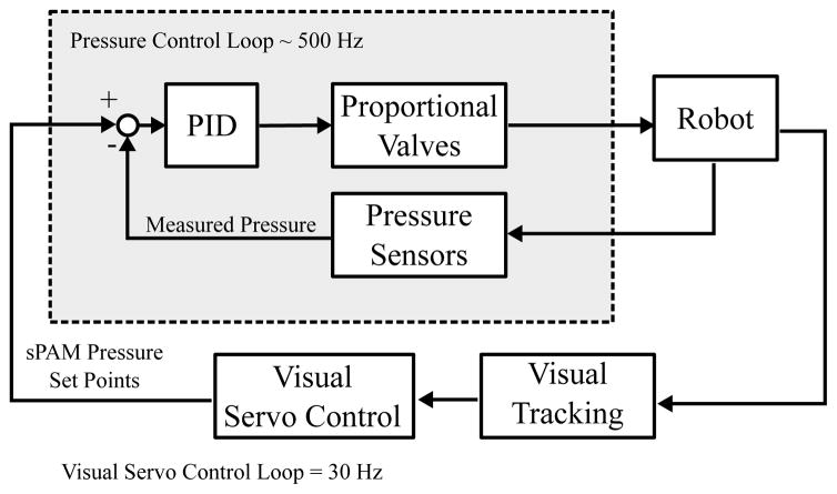
To control both the bending stiffness of the pneumatic backbone as well as the bending of the continuum robot, pressure in the main tube and each of the three sPAMs is regulated. Fig. 3 provides a high-level block diagram of the robot control architecture, in which the pneumatic system operates to regulate pressure. Pressure set-points for the pneumatic backbone and three sPAMs are regulated at 500 Hz by the pressure controller and commanded at 30 Hz by a visual servo controller (Section II-D). The pressure controller operates the pneumatic system, which consists of electronic proportional valves (EV-P-20-6050, Clippard Incorporated, Cincinnati, OH), that control air flow rates and analog pressure sensors (MPX5100DP-ND, Freescale Semiconductor, Austin, TX) from which pressure in the four chambers is measured for use in the pressure control loop.
Fig. 3.
Overview of robot control architecture. An eye-in-hand visual servo controller running at camera acquisition rates, 30 Hz, generates pressure set points for the pneumatic backbone and three sPAMs. A lower-level pressure controller running at approximately 500 Hz maintains these desired pressures in the four tubes.
D. Vision System
An eye-in-hand visual servo control law [22] is used to control the pose of the robot end-effector. Visual features are observed using a 170° field-of-view miniature camera mounted at the tip of the continuum robot (Fig. 11(b)) and measured by an image processing system (Sightline Applications Incorporated, Hood River, OR) at 30 Hz. The visual servo control law attempts to drive the location of a feature to a particular point in the camera’s field of view (e.g. the image center). This enables a human operator to control the robot via a simple interface in which he or she selects a visual feature in the camera’s field of view at which to point the continuum robot.
Fig. 11.
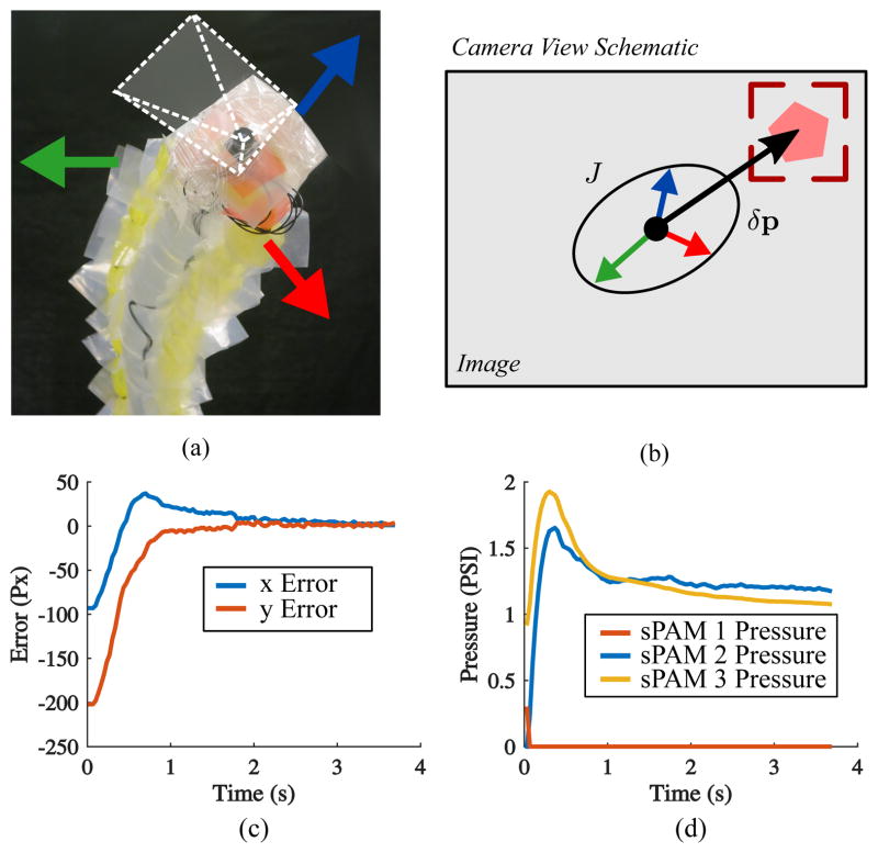
(a) Camera at end of continuum robot. Directions of tip movement are indicated by colored arrows. (b) Schematic of tip camera view. A visual servo controller drives image feature error δp (indicated by black arrow) to zero. Physically this corresponds to pointing the soft robot at the feature in track box. Image Jacobian, J, is visualized as an ellipse. Individual actuator directions are depicted as colored arrows (c) Step response pixel error of the visual servo controller during point-to-point tracking maneuver. (d) Commanded sPAM pressures for the step response.
III. Modeling
A. sPAM Model
In this section we present a model for the sPAM (Fig. 4). The purpose of this model is two-fold: (i) to establish a relationship between force and contraction, which is used in the robot’s kinematic model (Section III-B) and (ii) to understand what parameters are important for maximizing the contraction of the actuator. The main results are that the relationship between tension force and contraction ratio is approximately linear and that o-ring spacing and o-ring diameter must be appropriately chosen to maximize actuator performance.
Fig. 4.
(a) A sPAM segment starts as a thin sheet of length l0 and width W, which inflates to a Dtube = 2W/π diameter cylinder. (b) Adding an o-ring to the deflated actuator reduces its width to 2R through wrinkling and folding. (c) When it is inflated, the profile of the actuator bulges between the o-rings, causing it to contract to length l and exert a tension force, F. (d) A parallel circular cross-section of the sPAM, inflated by a pressure, p. It will satisfy zero parallel stress condition (σ = 0) if D < Dtube. (e) sPAMs attached to the pneumatic backbone, exerting forces F1, F2.
sPAMs use pressurized air to do work by changing the volume of the actuator [23]. This behavior is described by the load to length relation [24]
| (1) |
which shows that the tension force of the actuator is proportional to actuator pressure (p) and the change in volume (dV) per unit change in length (dL).
As described in Section II-A, sPAMs are constructed from a thin sheet of polyethylene tubing of length L, and width W, which inflates to a cylinder of diameter Dtube = 2W/π and length L. To create an sPAM with N segments, N + 1 o-rings of radius R are slid over the length of the actuator at regularly spaced intervals of length L/N = l0, we create N segments that contract when inflated (Fig. 4(a)–(b)). We model each of the N segments of the actuator as a modified pleated PAM (PPAM) which were analyzed by Dearden et al. in [23].
The defining characteristic of a PPAM is that as it inflates, its membrane radially unfurls, rather than stretches. This means that each parallel cross-section of the PPAM membrane has zero parallel stress (Fig. 4(d)) in all states of inflation. sPAMs also satisfy the zero parallel stress condition (i.e. they are effectively a series of PPAMs) when the diameter of the largest parallel cross section in the middle of the actuator is less than the diameter of the polyethylene tubing, Dtube. This is because expansion in the radial direction will occur as a result of unwrinkling and unfolding of its membrane. However, if the bulge radius of any of the sPAM sections exceeds Dtube, the sPAM no longer behaves as a PPAM as these sections have material stretching (Fig. 5). Here we explore the conditions under which the sPAM behaves like a PPAM.
Fig. 5.
(a) sPAM with o-ring spacing too large. Regions highlighted in red are where pleated PAM model predicts bulge radius larger than Dtube, and hence they do not contribute to contraction. (b) sPAM without inactive regions.
1) Pleated PAM model validity
First we provide a procedure to check whether a sPAM with a given set of dimensions, l0, R, and W will behave like a PPAM (zero-parallel stress condition). For a given contraction ratio, ε = 1 − l/l0, and assuming an inelastic material, the diameter of the largest cross-section can be computed from [7] as
| (2) |
where ϕR and m are constants that are defined by the following system of equations
| (3) |
where F( \ ), E( \ ) are the incomplete elliptic integrals of the first and second kind, respectively.
The diameter of a bulge of an sPAM increases monotonically with contraction, therefore we need to only check that the bulge diameter at maximum contraction is less than Dtube. To find εmax, we look at the tension force in the PPAM model [23]
| (4) |
where ϕR and m are defined by the system in Equation 3. When Fε = 0 (zero-tension), the actuator is at maximum contraction. To summarize, we can calculate whether the zero-stress condition is met by: (i) Calculating zero-tension contraction, εmax using Equation 4 and (ii) checking that Dεmax < Dtube using Equation 2.
2) Actuator parameters
The goal of this section is to find o-ring spacing that maximizes sPAM contraction, εmax. Calculated using Equation 4, Fig. 6(a) shows that for a PPAM, a slender actuator aspect ratio maximizes zero-tension contraction. However, the bulge diameter of the PPAM model increases as the actuator becomes more slender (Fig. 6(b)) until Dbulge = Dtube. When this happens, the sPAM diverges from the PPAM model. In particular, a portion of the actuator will become inactive and not contribute to contraction (Fig. 5). This occurs at the vertical dotted lines in Fig. 6(c). Therefore, zero-tension contraction is maximized when l0 is chosen so that Dbulge = Dtube. Practically, the plots in Fig. 6(a)–(c) may be used to maximize actuator contraction as follows: Assuming Dtube is set, o-ring diameter should be chosen as small as is practical. Finally, Fig. 6(c) may be used to find the optimal spacing between the sPAM o-rings.
Fig. 6.
(a) PPAM model predicts that a slender aspect ratio is optimal for maximizing contraction. (b) However bulge diameter increases with actuator slenderness until Dbulge = Dtube (Fig. 5). Bulge diameter curves are plotted for several values of R. (c) sPAM model for contraction as function of sPAM actuator radius. Contraction increases as sPAM becomes more slender, until Dbulge = Dtube (vertical dotted lines). Zero tension contraction is plotted for several values of R. (d) Actuator contraction vs. normalized tension force. PPAM behaves like a spring except when near full extension.
3) Actuator tension force
Using Equation 4, a tension force-displacement curve can be calculated for the sPAM. Fig. 6(d) shows the normalized force-displacement curve for a fixed actuator aspect ratio. We can see that the force-displacement curve is nearly linear except when the sPAM is near full extension. This allows us to approximate the actuator as a linear spring, which is used in the robot’s kinematic model (Section III-B).
B. Soft Continuum Robot Kinematic Model
Here we derive a forward kinematic model for the soft continuum robot. We make a simplifying assumption that the soft continuum robot bends in a constant curvature arc [13] and that the sPAMs act as linear springs. The forward kinematic model is a function of the three sPAM pressures p1, p2, p3 and the output of the model is the position of the end effector (tip of the continuum robot), x⃗ef ∈ ℝ3:
| (5) |
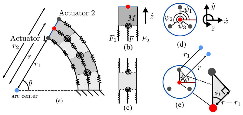
Our kinematic model is developed in two steps: (i) first we use constant curvature continuum robot length kinematics to relate tendon lengths, l1, l2, l3, to arc space parameters: backbone length, l, bending plane angle, ϕ, and pneumatic backbone radius of curvature, r (Fig. 7). (ii) Second, we use static equilibrium force conditions of the soft continuum robot to develop relationships between the sPAM pressures and robot end effector position using the constant curvature constraints from part (i).
Fig. 7.
(a) Kinematic model of constant curvature continuum robot. Cross-section in the bending plane of the continuum robot is shown. sPAMs are modeled as springs with stiffness controlled by actuator pressure. (b) End piece of spring system with forces acting on it. (c) Interior piece of spring system with forces acting on it. Sum of forces is always zero, independent of l and θ. (d) Head-on view of robot’s tip. Actuators are arranged radially around tip center at angles ψ1, ψ2, ψ3. (e) Head on view showing bending plane angle, ϕ and radii of curvatures of backbone and sPAM arc.
1) Constant curvature geometric kinematics
Here we review the work of Jones et al. [25] on the geometry of constant curvature continuum robots with direct control over tendon lengths, which computes arc-space parameters from side lengths. These will be used in step (ii). We assume that the positions of the actuators on the robot’s end piece, ψ1, ψ2, ψ3, which are specified in angles, are known (Fig. 7(d)). First we introduce three intermediate variables, which relate the positions of the actuators to the (unknown) position of the bending plane (Fig. 7(e)).
| (6) |
Using this definition, the robot tip geometry can be used to relate the (unknown) radii of curvatures of the three actuators to the (unknown) radius of curvature of the pneumatic backbone (Fig. 7(c))
| (7) |
Multiplying Equation 7 by θ (which is unknown) and using the relation li = θri we get
| (8) |
This yields three equations in our three unknown arc-space parameters, which can be solved.
2) Static force analysis
Here we use static force balance to relate our input pressures, p1, p2, p3, to arc space parameters, l, ϕ r:
| (9) |
| (10) |
where F, M are the moments and forces acting on the robot. In turn, the arc space parameters can be used to calculate x⃗ef.
The pneumatic backbone has stiffness that resists both bending and compression. To model these characteristics, we discretize the robot along its length into N rigid arc elements, each of which subtends an angle θ/N as shown in Fig. 7(a). The pneumatic backbone’s resistance to bending is captured as a series of torsion springs between each backbone segment with torsion spring constant, κ(N) and its resistance to axial compression is captured as a series of linear springs, each with stiffness K(N) and equilibrium length . We assume there is an underlying stiffness of the pneumatic backbone that is related to pressure and has an associated torsion and linear spring constant associated with it, κ and K, respectively. We relate the underlying stiffnesses to the discretized stiffnesses by the following scaling laws
| (11) |
as is standard with discrete spring models [26].
Next, we consider the sPAMs. Because the force-displacement curves of our sPAMs are approximately linear (Fig. 6(d)), we incorporate them into our model as linear springs. Each sPAM has a spring constant that scales linearly with pressure (Equation 1):
| (12) |
and an associated equilibrium length, . To incorporate our actuators into the distributed spring model, we break our actuators into N springs in series. Following the same convention as the main tube, we relate the N spring constants and equilibrium lengths to the actuator’s spring constant by the following scaling law
| (13) |
| (14) |
With all elements of the system defined, we consider equilibrium conditions of the system. Internal pieces of the spring system (Fig. 7(c)) are in equilibrium regardless of the kinematic parameters, therefore they are not considered. For an end-piece of the spring system (Fig. 7(b)) to satisfy equilibrium, we must have the sum of forces equal to zero:
| (15) |
as well as the sum of moments:
| (16) |
where Rz ( · ) is a rotation about the z-axis by a specified angle.
The force and moment balance relations (Equations 15 and 16) reduce to three scalar equations in six unknowns (ϕ, θ, l, l1, l2, l3). Including the geometric equations relating side lengths to l, ϕ, r (Equation 8) provides three more constraints, yielding a solvable system of six equations in six unknowns.
Finally, with l, ϕ, r computed, the end-effector position can be found. We define a coordinate system whose origin is at the base of the robot’s backbone curve. The coordinate system’s z-axis, ẑ, is tangent to the backbone curve and points to the tip of the robot, and x̂ and ŷ are chosen arbitrarily to define a right-handed coordinate system. With this coordinate system definition, we write x⃗ef as
| (17) |
| (18) |
IV. Experimental Validation
In this section, we describe validation experiments of both the sPAM model (Section III-A) and continuum robot kinematics (Section III-B).
A. sPAM Model Validation
To verify our sPAM model for contraction and force, experimental curves were generated for both the zero tension contraction ratio versus deflated length and force versus contraction.
1) Contraction experiments
Zero tension contraction is an important property of the sPAM that influences the maximum curvature of our soft continuum robot. To obtain a contraction curve, we varied the deflated length, l0, of the sPAM by varying the spacing of the sPAM o-rings. Deflated length and actuator radius (held constant) were measured using calipers. Zero tension contraction, εmax, was measured by inflating the sPAM, then measuring the length, l, between the actuator o-rings using calipers. εmax was calculated as l − l/l0.
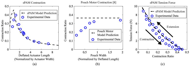
Fig. 8(a) compares the sPAM model to experimental contraction data. For the experiment, the sPAM radius and width were held constant and measured to be 0.25 cm, and 4.44 cm respectively. As predicted, we found that contraction increases as l0/W increases, in agreement with both the sPAM and PPAM models. As l0/W increases beyond approximately 1.5, the bulge diameter becomes greater than Dtube = 2W/π, and the sPAM diverges from the PPAM model. As expected, the contraction ratio falls off as 1/l0 because extra length does not contribute to contraction. For the parameters used in the experiment, a maximum contraction ratio of approximately 0.45 was predicted and a maximum contraction ratio of 0.4 was measured.
Fig. 8.
(a) Contraction predicted by sPAM model vs experimentally measured contraction, shown as a function of spacing between o-rings. A maximum contraction ratio of 0.4 is achieved experimentally. (b) Experimentally measured pouch motor contraction ratio, shown as a function of actuator width (Fig. 9). Pouch motor model predicts constant contraction because it ignores edge sealing. (c) Experimental force-displacement curve vs. predicted force-displacement curve.
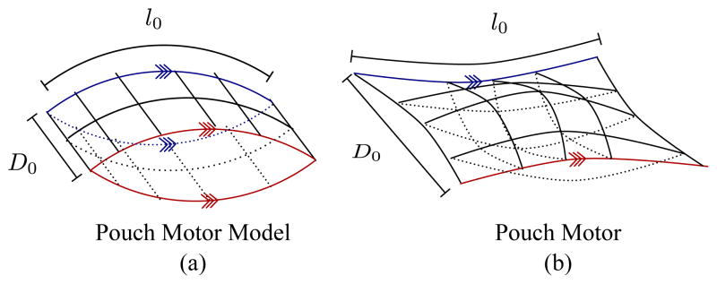
Fig. 8(b) shows experimental contraction data we collected for pouch motors [10] of comparable size to the sPAMs used in this work. Pouch motors were constructed from two polyethylene sheets that were 0.0508 mm thick and sealed on four sides. Deflated length, l0, was held constant at l0 = 5 cm. Actuator width, D, was varied. These parameters are depicted in Fig. 9. For each actuator width, the inflated length, l, was measured using calipers at in the middle of the pouch motor. The contraction curve demonstrates that the width of the pouch motor influences the maximum contraction ratio of the pouch motor despite the pouch motor model predicting a constant contraction ratio of approximately 0.36. We experimentally measured a maximum contraction ratio of 0.34, and the pouch motor approaches maximum contraction when the width to length ratio is approximately 1.
Fig. 9.
Comparison of (a) model of inflated pouch motor presented in [10] and (b) physical realization of inflated pouch motor with same dimensions. A pouch motor’s ends are sealed (red and blue contours), which means that they will overlap. The sealed ends reduces the maximum contraction attainable by a physical pouch motor and this effect becomes less pronounced as D0 increases.
2) Force Displacement Experiments
To verify the force model of the sPAM, we experimentally generated a force-displacement curve for the sPAM. sPAM pressure, radius, and deflated length were held constant at 10.34 kPA, 2 cm, and 2.5 mm for the duration of the experiment. One side of the sPAM was rigidly attached to a scale (M4–50, Mark-10 Corporation, Copiague, NY). A linear servo motor (Firgelli L16, Actuonix Motion Devices Incorporated, Victoria, B.C., Canda) was used to incrementally stretch the sPAM and its tension force was measured and recorded from the scale. Additionally, the sPAM was incrementally returned to maximum contraction (zero tension) and the tension force was measured and recorded during the return process.
Fig. 8(c) shows the sPAM force-displacement data that was collected using the procedure. We found the model to be accurate in predicting the force-displacement curve of the sPAM during the stretch phase of the experiment. As predicted, the sPAM was found to have a relatively linear force-displacement curve. During the return phase of the cycle, the sPAM’s forces were lower due to hystersis caused by actuator friction.
B. Kinematic Model Verification
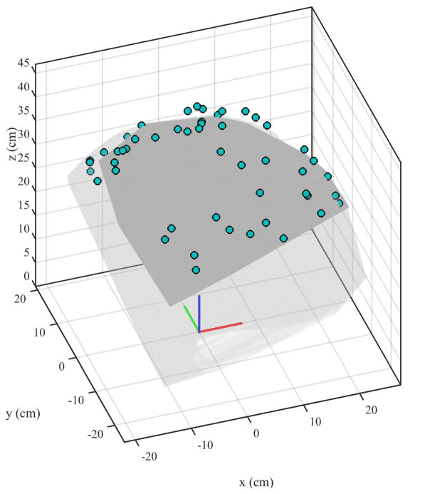
Our forward kinematic model described in Section III-B maps low-level control inputs (sPAM pressures, p1, p2, p3) to robot end-effector position, x⃗EF. To verify the model, an electromagnetic tracker (Ascension Model 800, Northern Digital Incorporated, Waterloo, ON, Canada) was attached near the tip of the continuum robot that was approximately 42 cm in length. We commanded 50 random sPAM pressure triples (p1, p2, p3) and recorded the pose of the robot end effector once it reached steady state. These 50 end effector poses are shown in Fig. 10 and provides a sense of the workspace of the robot.
Fig. 10.
Results of the kinematic model verification. Measured end-effector positions for 50 random pressure triples are displayed as solid circles. System identification was performed to determine parameters that best fit the measured positions. The resulting workspace is shown in dark grey and was calculated using the kinematic model. The light grey region was calculated by reducing torsion spring stiffness in the kinematic model, which corresponds to reducing pneumatic backbone pressure. As expected, the robot’s workspace is expanded.
Actuator positions, ψi were measured by commanding a displacement in each of the primary directions ([p1 = P, p2 = 0, p3 = 0]⊤, [p1 = 0, p2 = P, p3 = 0]⊤ and [p1 = 0, p2 = 0, p3 = P]⊤). In addition, a parameter identification was performed to find actuator and main tube equilibrium lengths, pressure spring constant factor (Equation 12), and main tube linear and torsion spring constants. The parameter identification was solved by finding the aforementioned parameter values that minimized the discrepancy between the predicted end-effector positions and measured end-effector positions. This was implemented using MATLAB’s fmincon routine.
With the parameter identification complete, we compared the predicted and measured robot end-effector position for each pressure triple. The circles in Fig. 10 show the measured positions of the robot’s end-effector. We found a mean discrepancy of 5.5 cm between prediction and measurement, which is slightly larger than the pneumatic backbone’s diameter (4.8 cm). Fig. 10 shows the robot’s approximate workspace in dark-grey. It was calculated by determining the end-effector position for randomly sampled pressure triples using the kinematic model and identified parameters. The light-grey region was calculated in the same way, but by reducing the main tube torsion spring constant. This corresponds to reducing main tube pressure. As expected, the robot’s workspace is enlarged.
V. Eye-in-Hand Control Demonstration
Fig. 11 provides an overview of the eye-in-hand visual servo control law [22] that was used in the demonstration. A camera is attached to the end of the continuum robot and a visual feature is designated (Fig. 11). The visual servo control law is responsible for generating the actuator pressures necessary to reorient the robot so that the robot is pointed toward the feature.
The visual servo control law uses an image Jacobian that maps changes in actuator inputs (in our case pressures) δp⃗ = [δp1, δp2, δp3]⊤ to image feature displacements δx⃗ = [δx, δy]⊤
| (19) |
For simplicity, we use an image Jacobian that is computed using a calibration procedure at the continuum robot’s zero actuator pressure configuration (straight up). We found that this image Jacobian is reasonably accurate throughout the entirety of its configuration space.
Fig. 11(c)–(d) show data taken from a point-to-point tracking maneuver. At time t = 0, a new feature is designated, providing a step input to the controller. As is seen from Fig. 11(c), the controller drives the image feature error to below 5% within 2 seconds, resulting in a rise and settling time of under 2 seconds. Rise time and settling time are limited by the maximum flow rate of the proportional valves used in this work (Section II-C).
Fig. 12 demonstrates the potential of our soft robot to manipulate objects through a simple pick and place experiment. We attached a vacuum gripper to the end of the robot and oriented the robot so that the gripper came into contact with a 50 gram box with visual servo control (Fig. 12(a)). By pressurizing the pneumatic backbone, the robot is able to apply enough vertical force to pick the box up (Fig. 12(b)) and place it at another location (shown in Fig. 12(c) just after release). Because the vacuum gripper was attached through the center of the tip of the robot, no torsional moments about the robot’s backbone were generated by the weight of the lifted object. The maximum weight the robot can lift is limited by transverse buckling of the robot’s backbone. This critical load to cause transverse buckling of an inflated beam is known to be F = πPR3/L, where F is the buckling force, R is the robot backbone radius, and P is the internal pressure of the robot [27]. Using the parameters of the robot, we found the maximum weight the robot can lift is approximately 200 grams. However it should be noted that lighter objects are used as controllability of the robot diminished with increasing object weight.
Fig. 12.
Pick and place maneuver. (a) The robot was oriented so that the vacuum gripper comes into contact with a box via visual servo control. (b) Pressurizing the pneumatic backbone results in the robot lifting the box upward. (c) Robot is maneuvered to place box in another location, shown here just after releasing the box.
VI. Conclusion and Future Work
This paper presented the design and fabrication of a new series pneumatic artificial muscle (sPAM) that was used as a soft tendon analog in a continuum robot. It was shown that as long as the sPAM’s deflated length is not too large, it is well modeled as a pleated PAM, which has been thoroughly analyzed in past work [7]. A static equilibirum kinematic model was presented and experimentally verified for the soft continuum robot that uses past work on geometric kinematics for constant curvature continuum robots. Finally, a proof-of-concept demonstration of control using an eye-in-hand visual servo control law was presented, showing the robot’s promise for real-time control. Future work includes adding additional degrees of freedom to the continuum robot, either through novel mechanisms or by stacking multiple constant curvature sections together, as well as developing a dynamic model of the robot’s motion and considering the effect of environmental contact on movement of the robot.
Acknowledgments
This work was supported in part by National Science Foundation grant 1441358, National Institutes of Health grant EB01884901, and a National Science Foundation Graduate Fellowship.
References
- 1.Rus D, Tolley MT. Design, fabrication and control of soft robots. Nature. 2015;521(7553):467–475. doi: 10.1038/nature14543. [DOI] [PubMed] [Google Scholar]
- 2.Neppalli S, Jones B, McMahan W, Chitrakaran V, Walker I, Pritts M, Csencsits M, Rahn C, Grissom M. Octarm-a soft robotic manipulator. IEEE/RSJ International Conference on Intelligent Robots and Systems. 2007:2569–2569. [Google Scholar]
- 3.Marchese AD, Komorowski K, Onal CD, Rus D. Design and control of a soft and continuously deformable 2d robotic manipulation system. IEEE International Conference on Robotics and Automation. 2014:2189–2196. [Google Scholar]
- 4.Brown E, Rodenberg N, Amend J, Mozeika A, Steltz E, Zakin MR, Lipson H, Jaeger HM. Universal robotic gripper based on the jamming of granular material. Proceedings of the National Academy of Sciences. 2010;107(44):18 809–18 814. [Google Scholar]
- 5.Asbeck AT, Dyer RJ, Larusson AF, Walsh CJ. Biologically-inspired soft exosuit. IEEE International Conference on Rehabilitation Robotics. 2013:1–8. doi: 10.1109/ICORR.2013.6650455. [DOI] [PubMed] [Google Scholar]
- 6.Tsagarakis NG, Caldwell DG. Development and control of a soft-actuated exoskeleton for use in physiotherapy and training. Autonomous Robots. 2003;15(1):21–33. [Google Scholar]
- 7.Daerden F. Conception and realization of pleated pneumatic artificial muscles and their use as compliant actuation elements. Vrije Universiteit Brussel; Belgium: 1999. [Google Scholar]
- 8.Trivedi D, Rahn CD, Kier WM, Walker ID. Soft robotics: Biological inspiration, state of the art, and future research. Applied Bionics and Biomechanics. 2008;5(3):99–117. [Google Scholar]
- 9.Klute GK, Czerniecki JM, Hannaford B. IEEE/ASME International Conference on Advanced Intelligent Mechatronics. 1999. Mckibben artificial muscles: pneumatic actuators with biomechanical intelligence; pp. 221–226. [Google Scholar]
- 10.Niiyama R, Sun X, Sung C, An B, Rus D, Kim S. Pouch motors: Printable soft actuators integrated with computational design. Soft Robotics. 2015;2(2):59–70. [Google Scholar]
- 11.Hawkes EW, Christensen DL, Okamura AM. Design and implementation of a 300% strain soft artificial muscle. IEEE International Conference on Robotics and Automation; IEEE; 2016. pp. 4022–4029. [Google Scholar]
- 12.Chou CP, Hannaford B. Measurement and modeling of mckibben pneumatic artificial muscles. IEEE Transactions on Robotics and Automation. 1996;12(1):90–102. [Google Scholar]
- 13.Webster RJ, Jones BA. Design and Kinematic Modeling of Constant Curvature Continuum Robots: A Review. The International Journal of Robotics Research. 2010;29(13):1661–1683. [Google Scholar]
- 14.Camarillo DB, Milne CF, Carlson CR, Zinn MR, Salisbury JK. Mechanics modeling of tendon-driven continuum manipulators. IEEE Transactions on Robotics. 2008;24(6):1262–1273. [Google Scholar]
- 15.Gravagne IA, Walker ID. Uniform regulation of a multi-section continuum manipulator. IEEE International Conference on Robotics and Automation. 2002;2:1519–1524. [Google Scholar]
- 16.Ohno H, Hirose S. Study on slime robot (proposal of slime robot and design of slim slime robot) IEEE/RSJ International Conference on Intelligent Robots and Systems. 2000;3:2218–2223. [Google Scholar]
- 17.Mahl T, Hildebrandt A, Sawodny O. A variable curvature continuum kinematics for kinematic control of the bionic handling assistant. IEEE Transactions on Robotics. 2014;30(4):935–949. [Google Scholar]
- 18.Marchese AD, Komorowski K, Onal CD, Rus D. Design and control of a soft and continuously deformable 2d robotic manipulation system. IEEE International Conference on Robotics and Automation. 2014:2189–2196. [Google Scholar]
- 19.Cianchetti M, Ranzani T, Gerboni G, De Falco I, Laschi C, Menciassi A. Intelligent Robots and Systems (IROS) IEEE; 2013. Stiff-flop surgical manipulator: mechanical design and experimental characterization of the single module; pp. 3576–3581. [Google Scholar]
- 20.Laschi C, Cianchetti M, Mazzolai B, Margheri L, Follador M, Dario P. Soft robot arm inspired by the octopus. Advanced Robotics. 2012;26(7):709–727. doi: 10.1088/1748-3182/7/2/025005. [DOI] [PubMed] [Google Scholar]
- 21.Stilli A, Wurdemann HA, Althoefer K. Intelligent Robots and Systems (IROS) IEEE; 2014. Shrinkable, stiffness-controllable soft manipulator based on a bio-inspired antagonistic actuation principle; pp. 2476–2481. [Google Scholar]
- 22.Flandin G, Chaumette F, Marchand E. Eye-in-hand/eye-to-hand cooperation for visual servoing. IEEE International Conference on Robotics and Automation. 2000;3:2741–2746. [Google Scholar]
- 23.Daerden F, Lefeber D. The concept and design of pleated pneumatic artificial muscles. International Journal of Fluid Power. 2001;2(3):41–50. [Google Scholar]
- 24.Chou CP, Hannaford B. Measurement and modeling of mckibben pneumatic artificial muscles. IEEE Transactions on Robotics and Automation. 1996;12(1):90–102. [Google Scholar]
- 25.Jones BA, McMahan W, Walker ID. Practical kinematics for real-time implementation of continuum robots. Proceedings - IEEE International Conference on Robotics and Automation. 2006;6:1840–1847. [Google Scholar]
- 26.Howell LL. Compliant Mechanisms. John Wiley & Sons; 2001. [Google Scholar]
- 27.Le van A, Wielgosz C. Bending and buckling of inflatable beams: some new theoretical results. Thin-walled structures. 2005;43(8):1166–1187. [Google Scholar]


