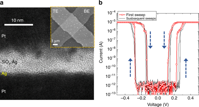
Fig. 2.
Memristor structure and electrical behavior. a High resolution cross-sectional TEM image of a diffusive memristor with a stack of Pt/SiOx:Ag/Ag/Pt. Inset shows the top-view SEM image of the cross-bar device with a junction area of 2.5 × 2.5 μm2. b Typical current–voltage (I–V) curves for the threshold switching under quasi-DC voltage sweeps. The very first switching events are in red and the subsequent curves are in gray. Blue arrows indicate the switching directions

