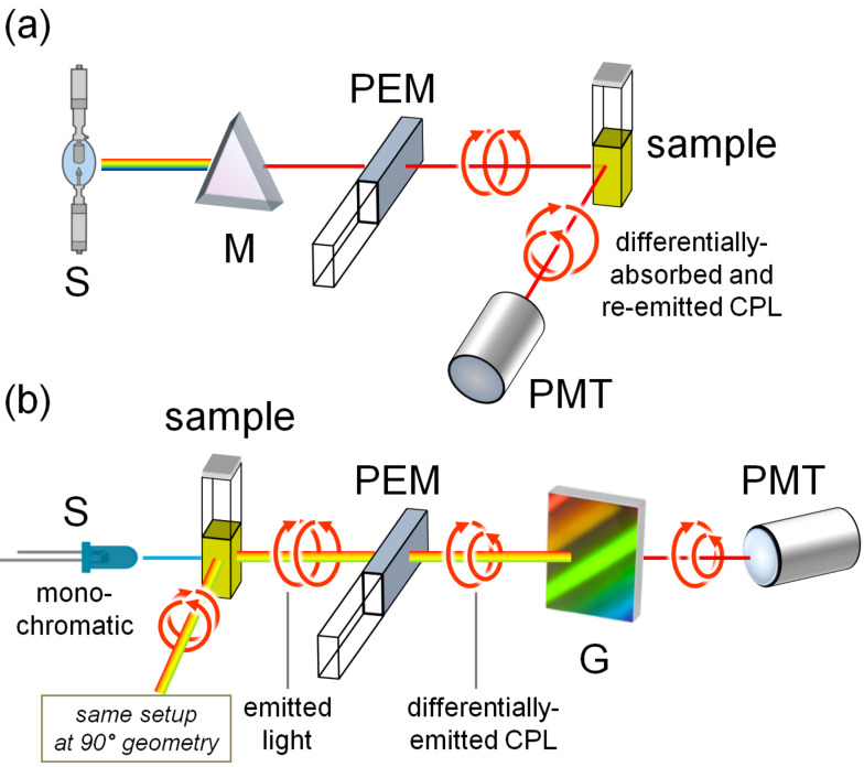
Figure 11.
Schematic illustration of an FDCD a) and a CPL b) instrument. Legend: S, source; M, monochromator (excitation wavelength selector); G, diffraction grating (emission wavelength selector); PEM, photoelastic modulator; PMT, photomultiplier (detector). In CPL, both 0° and 90° setups are possible; in FDCD, the 90° setup is used.

