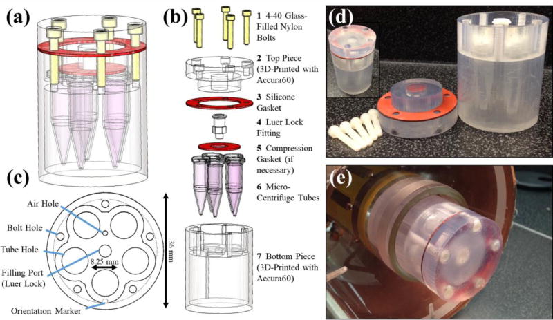
Figure 1.
The schematic design of the MRI phantom is shown as a 3D CAD model (a) and in an exploded view (b) with parts (custom and purchased) listed. An axial view of bottom piece (c) depicts several design features including the air hole and filling port for air release and water filling, respectively. A notch is included as an orientation marker in filled mode along one of the micro-centrifuge tube holes. The overall maximum diameter of the phantom is 36 mm with room for five micro-centrifuge tubes with 8.25 mm diameters each. Photographs of both the disassembled phantom (d) and the assembled phantom outside (d, inset) and within the RF imaging coil (e) are also shown.

