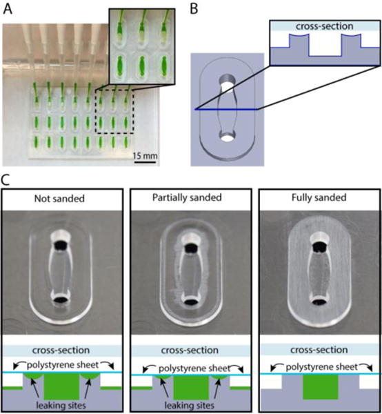
Figure 6.

Closed channel cell culture device fabricated by solvent bonding a PS sheet (comprising the channel floor) and a PS injection molded device (comprising the channel walls and ceiling). (A) Closed channel cell culture device with multiplexed channel filling using a multichannel pipette. (B) Schematic of a single channel with oval island surrounding the channel. The cross-section (inset) shows that the oval island surrounding the channel is slightly curved due to plastic sinking caused by variable cooling rates of thick and thin regions of the injection molded device. (C) Schematic diagrams illustrating channel cross sections after solvent bonding to a PS sheet. For clarity the orientation of the schematic matches the orientation of the photographs directly above; when in operation, the device is flipped over such that the PS sheet forms the floor (as shown in A). The schematic diagrams indicate the results of filling the solvent bonded devices with fluid (green); leaking occurs when devices are assembled without sanding. Sanding provides a flat surface for solvent bonding enabling a leak-free device. Photographs show whitened areas of plastic removed by sanding the oval islands.
