
Fig. 2.
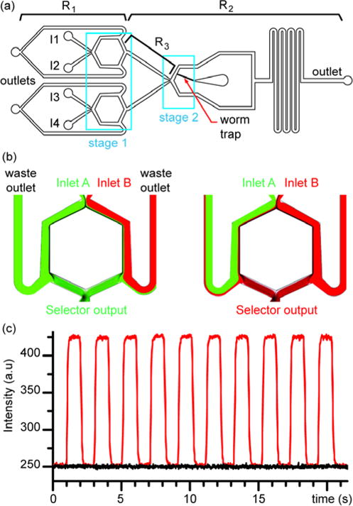
Platform design. (a) Device design integrates three chemical selectors distributed in two stages. First stage allows for selecting two chemicals that feed the second stage to select the stimulus present at the worm’s head. Optimization of balance in resistances is necessary: R1/R2 relates to the sensitivity to pressure variation to achieve chemical switch; R3 must prevent backflow when switching inlet pressures while allowing for brief residential time to ensure sub-second chemical switch. (b) Upstream chemical selector unit design. COMSOL simulation demonstrating the on-demand selection of stimulus 1 or 2 depending on inlet pressure A and B. (c) Experimental validation of the chemical selector unit by injecting a fluorescent dye solution in inlet1 and a non-fluorescent solution in inlet2. Intensity monitored at the output “selected chemical” shows square signal (red curve) reflecting the modulation of pressure commands at inlet A. Background intensity (black curve) gives a baseline of reference to demonstrate the full removal of the dye solution during alternations.