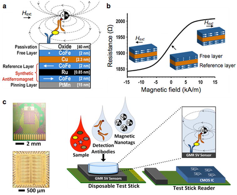
Figure 4. Giant magnetoresistance (GMR) magnetometer.

(a) GMR sensors have multiple layers of magnetic and non-magnetic materials. The magnetization of a reference layer is fixed through indirect exchange coupling in the synthetic antiferromagnet. The magnetization of the free layer, however, can rotate in response to the external magnetic field strength (Hext). (b) Due to the spin-dependent electron scattering, the electrical resistance of a GMR sensor changes as a function of the relative magnetization angle between the free and the reference layers. (c) An array of 256 GMR sensors (top) and its interface CMOS chip (bottom) were separately fabricated. The GMR sensor was mounted on a disposable test stick, and interfaces with the stick reader. A sandwich assay was used to detect protein markers. CMOS, complementary metal-oxide-semiconductor. Reproduced with permission from Ref. 59. Copyright 2013 IEEE.
