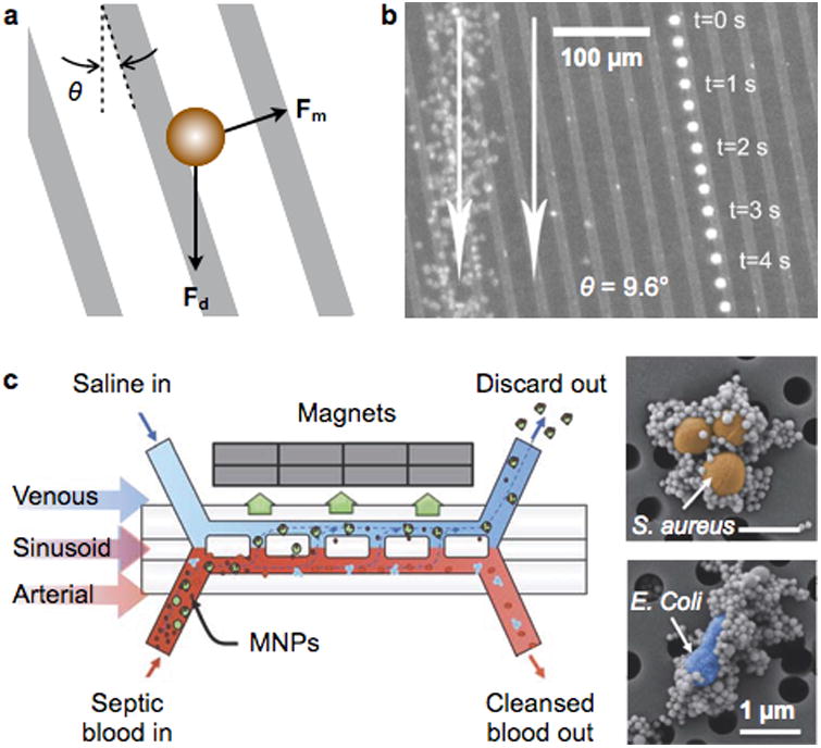
Figure 8. In-flow magnetic separation devices.

(a) An array of magnetic lines are used to divert the trajectory of magnetic objects in flow. The magnetic lines are magnetized out of plane, and aligned at an angle θ with respect to the flow direction. The net force on the object is the vector sum of the in-plane magnetic force (Fm) and the fluid drag force (Fd). (b) Time lapse image showing a single magnetically-tagged leukocyte. Red blood cells on the left are from a single image. The leukocyte tracks a magnetic line oriented at an angle of 9.6° to the fluidic flow (white arrow). (c) A two-channel microfluidic device to separate MNP-labeled bacteria in blood, mimicking the spleen structure. The device mimics the structure of the spleen by incorporating a high-flow vascular arterial channel interconnected by open slits to a parallel low- or intermittent-flow venous sinusoid channel. Magnetic particles are mixed with blood sample to label pathogens (inset), and the mixture is introduced to the arterial channel. Reprinted with permission from Ref. 86. Copyright 2004 American Institute of Physics. Reprinted with permission from Ref. 100. Copyright 2014 Nature Publishing Group.
