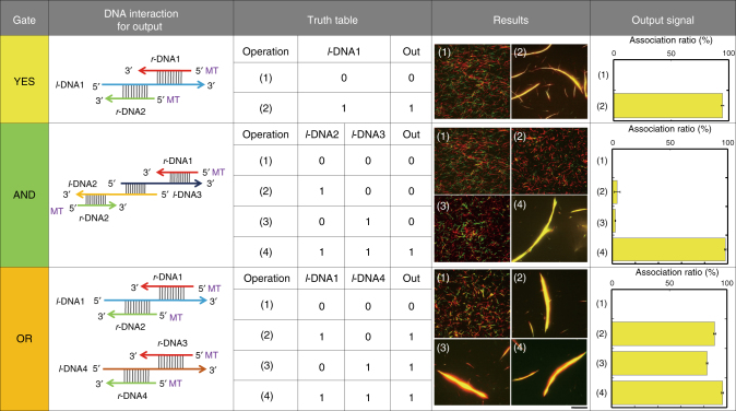
Fig. 2.
Design of logic gates constructed with MTs. For the YES gate, the l-DNA1 signal was inputted into the system and swarming was obtained as the output signal (1 to 1). For the AND gate, l-DNA2 and l-DNA3 had both to be present to obtain swarming. For the OR gate, the presence of either l-DNA1 or l-DNA4 was sufficient to obtain swarming. The concentration of red and green MTs was 0.6 µM, and the conjugation ratio of each r-DNA to MTs was ~100%. The concentration of kinesin and each l-DNA was 0.3 µM and 0.6 µM, respectively. Scale bar: 20 µm. Error bars: s.e.m.

