Abstract
Regularly spaced TiO2 nanotubes were prepared by anodizing a titanium substrate in triethylene glycol electrolyte at elevated temperature. In comparison to conventional TiO2 nanotubes, spaced nanotubes possess an adjustable spacing between the individual nanotubes; this allows for controlled buildup of a hierarchical nanoparticle‐on‐nanotube structure. Here, we use this principle for layer‐by‐layer decoration of the tubes with TiO2 nanoparticles. The hierarchical structure after N doping and NH3 treatment at 450 °C shows a significant enhancement of visible‐light absorption, although it only carries a low doping concentration of nitrogen. For optimized N‐doped and particle‐decorated spaced TiO2 nanotubes, a considerable improvement in photocatalytic activity is obtained in comparison with conventional N‐doped TiO2 nanotubes or comparable N‐doped nanoparticle films. This is attributed to an enhanced visible‐light absorption through the N‐doped nanoparticle shell and a fast charge separation between the shell and the one‐dimensional nanotubular core.
Keywords: hierarchical structures, nitrogen doping, photocatalysis, spaced TiO2 nanotubes, visible-light absorption
Ever since the groundbreaking work of Fujishima and Honda1 on the photoelectrochemical splitting of water on TiO2 electrodes, TiO2 has become the most investigated semiconductor material for photoelectrolysis of water to hydrogen and oxygen and for the photodegradation of organic compounds in a liquid or gas environment.1, 2, 3, 4, 5, 6, 7, 8, 9, 10, 11, 12 However, owing to its wide band gap (ca. 3.2 eV for anatase), photocatalysis in TiO2 can only be activated under UV‐light irradiation, which contributes only around 5 % to the total energy of solar spectrum.13 Therefore, introducing modifications that allow the use of TiO2 in both UV and visible light to enhance the photocatalytic efficiency is of great significance. Many efforts have been dedicated to establishing the absorption of TiO2 for visible light, including sensitizing TiO2 with dyes5, 14 and doping TiO2 with metal (V, Fe, Mn) or non‐metal (N, C, S, B) elements that form p‐states near the valence band of TiO2.15, 16, 17, 18, 19, 20, 21, 22, 23 Alternatively, cation doping results in localized d‐states deep in the band gap of TiO2, but also leads to a lower activity through the formation of recombination centers.16
The most widely and successfully used approach for visible‐light absorption is to dope TiO2 with nitrogen, which results in photocatalytic activity under visible‐light irradiation.18, 24 Asahi et al. proposed that the TiO2 band gap becomes narrower because the delocalized N2p state of the dopant mixes with the O2p valence band of TiO2.24 Others proposed that N doping induces a higher energy valence band caused by the high density of localized N2p states in the band structure of TiO2.25, 26 In either case, low‐energy photons in the visible region can excite electrons from these occupied high‐energy states to the conduction band of TiO2. For photocatalytic reactions, after excitation, generated electrons and holes migrate to the surface and are then transferred to redox couples in the electrolyte. In spite of the advantages of N doping, the process induces recombination states for electron–hole pairs that can significantly reduce carrier lifetime, that is, N‐doped TiO2 typically provides only short carrier diffusion lengths.27
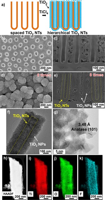
To overcome this drawback, herein we introduce a hierarchical structure based on the formation of a spaced TiO2 nanotube (NT) core as a current conductor decorated with suitable TiO2 nanoparticle (NP) layers. Spaced NT layers can be formed with a large and adjustable spacing between them that allows for a defined layer‐by‐layer coating of TiO2 NPs on the wall of the NTs (Figure 1 a). These decorated NTs then can be annealed in NH3 atmosphere to induce N doping of the TiO2 NPs on the TiO2 core, that is, a hierarchical structure that shows an enhanced photocatalytic performance. The key here is that spaced NTs allow for a controlled NP decoration; thus, the structure provides both an enhanced surface area and facilitated electron‐transport properties when optimally designed.
Figure 1.

a) Fabrication of spaced TiO2 NTs decorated with layer‐by‐layer TiO2 NPs. SEM images of: b, c) as‐formed spaced TiO2 NTs; d, e) spaced TiO2 NTs decorated with eight layers of NPs. f, g) TEM images of spaced TiO2 NTs decorated with eight layers of NPs. h) HAADF and i–k) elemental mappings of spaced TiO2 NT decorated with TiO2 NPs.
Figures 1 b and 1 c show SEM images of spaced TiO2 NTs after anodization in a hot triethylene‐glycol‐based electrolyte containing NH4F and H2O (see the Experimental Section in the Supporting Information). The individual NTs have a length of 3 μm and a diameter of 170 nm. It is apparent that each NT is separated from the others, leaving a space of approximately 200 nm between individual tubes.28, 29, 30 This distance is used to decorate the individual NT walls with TiO2 NPs by using a TiCl4 hydrolysis approach.14, 31 In fact, the inter‐tube spacing is sufficiently large that the TiCl4 treatment can be repeated several times to decorate the NT walls in a layer‐by‐layer approach, thereby maximizing the specific surface area.29, 30, 32 Figures 1 d and 1 e show SEM images of spaced TiO2 NTs after eight layers of decoration. Accordingly, the outer diameter of particle‐decorated NTs increases after each layer of TiO2 particles, whereas the inner diameter decreases. The inner part of the spaced NTs is completely filled with NPs after five layers of decoration and the outer part is filled up after the eighth layer (Figure S1). In these structures, the TiO2 NPs have an average diameter of approximately 5–10 nm, and the thickness of each particle layer is approximately 17 nm. The decorated tubes were then annealed in air at 450 °C in order to fully convert the tubes and NPs into anatase. High‐resolution transmission electron microscopy (HR‐TEM) analysis also confirms that, after decoration, the TiO2 NPs consist of anatase with a (101) lattice spacing of 3.48 Å (Figures 1 f and 1 g).33 The high‐resolution annular dark‐field (HAADF) image and elemental mappings in Figures 1 h–k reveal that the NPs consist of TiO2. Furthermore, fluoride ions (from the anodization process) and spurious carbon remain on the NT walls. It should be noted that it is particularly difficult to distinguish N(Kα1) and Ti(Lα1) because of overlapping peaks.34
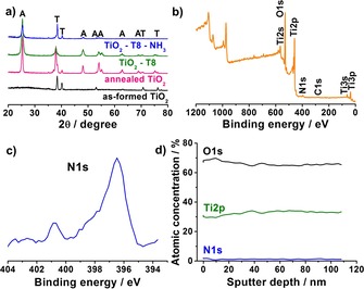
The decorated spaced NTs were then annealed in the NH3 environment at 450 °C for 3 h to induce N doping of the TiO2. In the XRD patterns, the intense peak at 2θ=25.3° (Figure 2 a) remains present, corresponding to the anatase phase after the previous thermal treatment in air at 450 °C. That is, after NH3 treatment, the crystallography of the samples remains unchanged although the intensity of anatase peaks slightly decreases. Successful N doping is confirmed by the appearance of N 1s peak at 396.5 eV in the XPS spectra (Figures 2 b and 2 c).24, 26, 35, 36 Furthermore, the concentration of nitrogen is approximately 2.4 at % and it remains unchanged even at a depth of 100 nm (Figure 2 d). This indicates that N doping occurs not only on the surface, but also within the TiO2 structure.
Figure 2.

a) XRD patterns of as‐formed spaced TiO2 NTs, annealed spaced TiO2 (450 °C air 1 h), spaced TiO2 NTs decorated with eight layers of NPs and N‐doped spaced TiO2 NTs decorated with eight layers of TiO2 NPs (A=anatase, T=titanium). b) XPS spectrum and c) N 1s peaks of N‐doped spaced TiO2 NTs decorated with eight layers of NPs. d) XPS depth profile of N‐doped spaced TiO2 NTs decorated with eight layers of NPs.
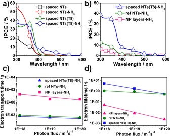
The N‐doped samples were then investigated with photocurrent spectra (Figures 3 a and 3 b). The N‐doped samples show significant enhancement of incident photon‐to‐current efficiency (IPCE) in the visible‐light range. The results in Figure 3 a also reveal that NP decoration can enhance the IPCE (at 450 nm) almost fivefold, in comparison with plain spaced NTs (1 and 5 %, respectively). We found that the maximum IPCE for spaced NTs is obtained after eight layers of decoration and 3 h of NH3 treatment, whereas lower or higher loadings of TiO2 particles led to a decrease of photocurrent under visible‐light irradiation (Figures S2 and S3). Figure S4 shows the IPCE of different lengths of spaced TiO2 NTs decorated with eight layers of NPs. We found that the longer the spaced NTs, the higher the IPCE in the visible range. A maximized IPCE was obtained for 10 μm long tubes (Figure S5). The results of photoelectrochemical measurements under visible light show that the N‐doped hierarchical structures can be used to more efficiently harvest photocurrent than corresponding non‐doped layer (Figure S6).
Figure 3.

IPCE spectra of a) spaced TiO2 NTs with/without eight layers of TiO2 NPs and N‐doped spaced TiO2 NTs with/without eight layers of TiO2 NPs; b) N‐doped reference NTs, spaced NTs with eight layers of TiO2 NPs and NP layers on FTO. c) Electron transfer time constants from IMPS measurements and d) electron lifetime constants from IMVS measurements under visible‐light illumination (λ=530 nm) for different N‐doped samples.
Figure 3 b shows the IPCE results of different samples that illustrate the main difference of the hierarchical NTs, compared with classic close‐packed TiO2 NTs (denoted NTs‐NH3, Figure S7) and TiO2 NP layers on FTO substrate (prepared through the doctor blading method, denoted NP layers‐NH3). In general, NP layers‐NH3 deliver a much lower photocurrent compared to NT samples, owing to the high recombination of electrons and holes in the NP layers.37 Furthermore, under visible light (at 450 nm), the IPCE value of spaced NTs is 5.19 %—that is over seven times higher than that measured for classic TiO2 NTs (0.66 %). This is ascribed to the much higher particle loading of the spaced NTs and the higher surface area resulting from several layers of TiO2 NP decoration.29, 30, 38
Additionally, TiO2 NP decoration obtained from TiCl4 treatments on TiO2 NTs has been reported to be able to passivate surface states of NTs, thereby strongly reducing the recombination centers.39 This benefit is also examined in the present work by intensity‐modulated photocurrent spectroscopy (IMPS) and intensity‐modulated voltage spectroscopy (IMVS). Herein, IMPS and IMVS measurements were carried out under visible light (530 nm) (Figures 3 c and 3 d). It is found that the spaced NTs decorated with TiO2 NPs show a significantly faster electron transport time in comparison with conventional NTs, and the transport rate is a hundred times faster than NP layers on FTO. Furthermore, Figure 3 d shows that the electron lifetime constants for the spaced NTs with NPs are one and two orders of magnitude longer than for classic NTs and NP layers, respectively. This indicates that the TiCl4 treatment associated with NP decoration can passivate the defects on TiO2 NTs, thereby clearly improving the electronic properties.40
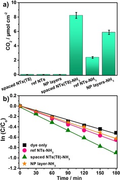
To evaluate the efficiency of the hierarchical structure not only on the photoelectrochemical properties—as described above—but also on photocatalytic effects, we investigated classic target models for photocatalysis in gas form (acetaldehyde) and in liquid form (methylene blue). To test for an activated visible‐light response in the gas phase, we examined the above hierarchical structures for the photodegradation of acetaldehyde under solar simulator AM 1.5 conditions with a 420 nm cut‐off filter. Figure 4 a shows the amount of photocatalytic CO2 generated for spaced NTs, compared to NTs and TiO2 particle layers, after an 8 h irradiation. The results clearly indicate that, as expected, no visible‐light photocatalytic activity was detected for non‐doped samples. However, all the investigated N‐doped materials show visible‐light activity, and clearly the N‐doped hierarchical spaced NTs show by far the largest amount of generated CO2 in comparison with N‐doped NTs or NP layers on FTO (8 μmol cm−2 compared to 2 and 6 μmol cm−2, respectively). Furthermore, these N‐doped hierarchical spaced‐NTs exhibit a linear CO2 evolution rate, indicating that the structures and doping are stable over time under these irradiation conditions (Figure S8).
Figure 4.

a) Photocatalytic CO2 evolution during the photodegradation of acetaldehyde and b) photodegradation of methylene blue under visible‐light irradiation (solar simulator AM 1.5, 100 mW cm−2, 420 nm cut‐off filter) for different samples.
The photocatalytic activity of the N‐doped samples in liquid solution were further studied by means of photodecomposition of methylene blue aqueous solution under visible‐light irradiation (Figure 4 b). Also in these experiments, the photocatalytic activity of hierarchical spaced NTs shows the highest efficiency of all N‐doped samples. In all of these photocatalytic experiments, the better performance of the hierarchical spaced NTs can be attributed to two factors: the combination of high‐NP loading providing a high surface area and the electronic features of the core–shell structure.
Regarding the electronic properties, the photoelectrochemical experiments clearly show an enhanced electron mobility for the core–shell structure compared to the particle structure. This leads to swift electron transport away from the buried particle/core interface, that is, a fast carrier separation is likely the origin for the enhanced photocatalytic activity. Based on thermal diffusion gradients during N doping, it is plausible that the highest doping and, thus, the highest density of N states above the TiO2 valence band will be reached in the outermost part of the structure; this provides an additional graded n–n junction within the hierarchical structure that may additionally contribute to carrier separation and the significantly enhanced activity observed of the hierarchical tube–particle structure compared with plain NP layers.
In summary, we demonstrate in the present work that spaced NT arrays provide a valuable platform to construct efficient hierarchical structures—in the present case to ideally exploit N‐doped TiO2 materials for photoelectrochemical applications and for visible light photocatalysis. In these structures, already light N doping of these 1D structures leads to significant visible‐light absorption, owing to their geometry. Such structures show strong visible‐light‐generated photocurrents and an enhanced photocatalytic performance under visible‐light irradiation. In comparison, the spaced TiO2 NTs after NP decoration yields significantly higher photocatalytic activity, not only as compared with conventional NTs, but also with conventional TiO2 NP layers. The enhancement in efficiency of spaced TiO2 NTs can firstly be attributed to the space between the NTs, which allows for a large particle loading, thus increasing the surface area, and secondly to superior electronic properties provided by these structures. The strategy used here opens the opportunity to deposit other materials into the space between TiO2 NTs in order to produce, for instance, a full range controlled electronic junctions in aligned 1D TiO2‐based structures.41
Conflict of interest
The authors declare no conflict of interest.
Supporting information
As a service to our authors and readers, this journal provides supporting information supplied by the authors. Such materials are peer reviewed and may be re‐organized for online delivery, but are not copy‐edited or typeset. Technical support issues arising from supporting information (other than missing files) should be addressed to the authors.
Supplementary
Acknowledgements
The authors would like to acknowledge Bernadeta Hack for technical help. Xuemei Zhou is acknowledged for XPS measurements. We would also like to acknowledge the ERC, the DFG, the Erlangen DFG cluster of excellence EAM, EXC 315 (Bridge), the DFG funCOS and the Operational Programme Research, Development and Education ‐ European Regional Development Fund, project no. CZ.02.1.01/0.0/0.0/15 003/0000416 of the Ministry of Education, Youth and Sports of the Czech Republic for financial support.
N. T. Nguyen, S. Ozkan, O. Tomanec, R. Zboril, P. Schmuki, ChemistryOpen 2018, 7, 131.
References
- 1. Fujishima A., Honda K., Nature 1972, 238, 37–38. [DOI] [PubMed] [Google Scholar]
- 2. Fujishima A., Zhang X., Tryk D., Surf. Sci. Rep. 2008, 63, 515–582. [Google Scholar]
- 3. Khan S. U. M., Al-Shahry M., W. B. Ingler, Jr. , Science 2002, 297, 2243–2245. [DOI] [PubMed] [Google Scholar]
- 4. Ni M., Leung M. K. H., Leung D. Y. C., Sumathy K., Renewable Sustainable Energy Rev. 2007, 11, 401–425. [Google Scholar]
- 5. O'Regan B., Grätzel M., Nature 1991, 353, 737–740. [Google Scholar]
- 6. Zhu K., Neale N. R., Miedaner A., Frank A. J., Nano Lett. 2007, 7, 69–74. [DOI] [PubMed] [Google Scholar]
- 7. Kormann C., Bahnemann D. W., Hoffmann M. R., Environ. Sci. Technol. 1988, 22, 798–806. [DOI] [PubMed] [Google Scholar]
- 8. Ibusuki T., Takeuchi K., Atmos. Environ. 1986, 20, 1711–1715. [Google Scholar]
- 9. Gao F., Wang Y., Shi D., Zhang J., Wang M., Jing X., Humphry-Baker R., Wang P., Zakeeruddin S. M., Grätzel M., J. Am. Chem. Soc. 2008, 130, 10720–10728. [DOI] [PubMed] [Google Scholar]
- 10. Konstantinou I. K., Albanis T. A., Appl. Catal. B 2004, 49, 1–14. [Google Scholar]
- 11. Lee K., Mazare A., Schmuki P., Chem. Rev. 2014, 114, 9385–9454. [DOI] [PubMed] [Google Scholar]
- 12. Riboni F., Nguyen N. T., So S., Schmuki P., Nanoscale Horiz. 2016, 1, 445–466. [DOI] [PubMed] [Google Scholar]
- 13. Chen X., Mao S. S., Chem. Rev. 2007, 107, 2891–2959. [DOI] [PubMed] [Google Scholar]
- 14. Nazeeruddin M. K., Kay A., Rodicio I., Humphry-Baker R., Mueller E., Liska P., Vlachopoulos N., Graetzel M., J. Am. Chem. Soc. 1993, 115, 6382–6390. [Google Scholar]
- 15. Ohno T., Akiyoshi M., Umebayashi T., Asai K., Mitsui T., Matsumura M., Appl. Catal. A 2004, 265, 115–121. [Google Scholar]
- 16. Choi W., Termin A., Hoffmann M. R., J. Phys. Chem. 1994, 98, 13669–13679. [Google Scholar]
- 17. Kumar S. G., Devi L. G., J. Phys. Chem. A 2011, 115, 13211–13241. [DOI] [PubMed] [Google Scholar]
- 18. Asahi R., Morikawa T., Irie H., Ohwaki T., Chem. Rev. 2014, 114, 9824–9852. [DOI] [PubMed] [Google Scholar]
- 19. Roy P., Berger S., Schmuki P., Angew. Chem. Int. Ed. 2011, 50, 2904–2939; [DOI] [PubMed] [Google Scholar]; Angew. Chem. 2011, 123, 2956–2995. [Google Scholar]
- 20. Nah Y.-C., Paramasivam I., Schmuki P., Chemphyschem 2010, 11, 2698–2713. [DOI] [PubMed] [Google Scholar]
- 21. Péchy P., Renouard T., Zakeeruddin S. M., Humphry-Baker R., Comte P., Liska P., Cevey L., Costa E., Shklover V., Spiccia L., Deacon G. B., Bignozzi C. A., Grätzel M., J. Am. Chem. Soc. 2001, 123, 1613–1624. [DOI] [PubMed] [Google Scholar]
- 22. Anpo M., Takeuchi M., J. Catal. 2003, 216, 505–516. [Google Scholar]
- 23. Sakthivel S., Kisch H., Angew. Chem. Int. Ed. 2003, 42, 4908–4911; [DOI] [PubMed] [Google Scholar]; Angew. Chem. 2003, 115, 5057–5060. [Google Scholar]
- 24. Asahi R., Morikawa T., Ohwaki T., Aoki K., Taga Y., Science 2001, 293, 269–271. [DOI] [PubMed] [Google Scholar]
- 25. Di Valentin C., Pacchioni G., Selloni A., Phys. Rev. B 2004, 70, 85116. [Google Scholar]
- 26. Batzill M., Morales E. H., Diebold U., Phys. Rev. Lett. 2006, 96, 26103. [DOI] [PubMed] [Google Scholar]
- 27. Irie H., Watanabe Y., Hashimoto K., J. Phys. Chem. B 2003, 107, 5483–5486. [Google Scholar]
- 28. Özkan S., Nguyen N. T., Mazare A., Cerri I., Schmuki P., Electrochem. Commun. 2016, 69, 76–79. [Google Scholar]
- 29. Nguyen N. T., Ozkan S., Hwang I., Mazare A., Schmuki P., Nanoscale 2016, 8, 16868–16873. [DOI] [PubMed] [Google Scholar]
- 30. Nguyen N. T., Ozkan S., Hwang I., Zhou X., Schmuki P., J. Mater. Chem. A 2017, 5, 1895–1901. [Google Scholar]
- 31. Roy P., Kim D., Paramasivam I., Schmuki P., Electrochem. Commun. 2009, 11, 1001–1004. [Google Scholar]
- 32. Sun L., Zhang S., Wang X., Sun X. W., Ong D. Y., Wang X., Zhao D., ChemPhysChem 2011, 12, 3634–3641. [DOI] [PubMed] [Google Scholar]
- 33. Nguyen N. T., Altomare M., Yoo J. E., Taccardi N., Schmuki P., Adv. Energy Mater. 2016, 6, 1501926. [Google Scholar]
- 34. Xue L., Islam M., Koul A. K., Bibby M., Wallace W., Adv. Perform. Mater. 1997, 4, 389–408. [Google Scholar]
- 35. Lu X., Wang G., Zhai T., Yu M., Xie S., Ling Y., Liang C., Tong Y., Li Y., Nano Lett. 2012, 12, 5376–5381. [DOI] [PubMed] [Google Scholar]
- 36. Nakajima T., Lee C., Yang Y., Schmuki P., J. Mater. Chem. A 2013, 1, 1860–1866. [Google Scholar]
- 37. Cowan A. J., Tang J., Leng W., Durrant J. R., Klug D. R., J. Phys. Chem. C 2010, 114, 4208–4214. [Google Scholar]
- 38. Wang X., Sun L., Zhang S., Wang X., Huo K., Fu J., Wang H., Zhao D., RSC Adv. 2013, 3, 11001–11006. [Google Scholar]
- 39. So S., Hwang I., Schmuki P., Energy Environ. Sci. 2015, 8, 849–854. [Google Scholar]
- 40. Adli H. K., Harada T., Nakanishi S., Ikeda S., Phys. Chem. Chem. Phys. 2017, 19, 26898–26905. [DOI] [PubMed] [Google Scholar]
- 41. Zhao X., Huang J., Wang Y., Xiang C., Sun D., Wu L., Tang X., Sun K., Zang Z., Sun L., Electrochim. Acta 2016, 199, 180–186. [Google Scholar]
Associated Data
This section collects any data citations, data availability statements, or supplementary materials included in this article.
Supplementary Materials
As a service to our authors and readers, this journal provides supporting information supplied by the authors. Such materials are peer reviewed and may be re‐organized for online delivery, but are not copy‐edited or typeset. Technical support issues arising from supporting information (other than missing files) should be addressed to the authors.
Supplementary


