
Figure 1.
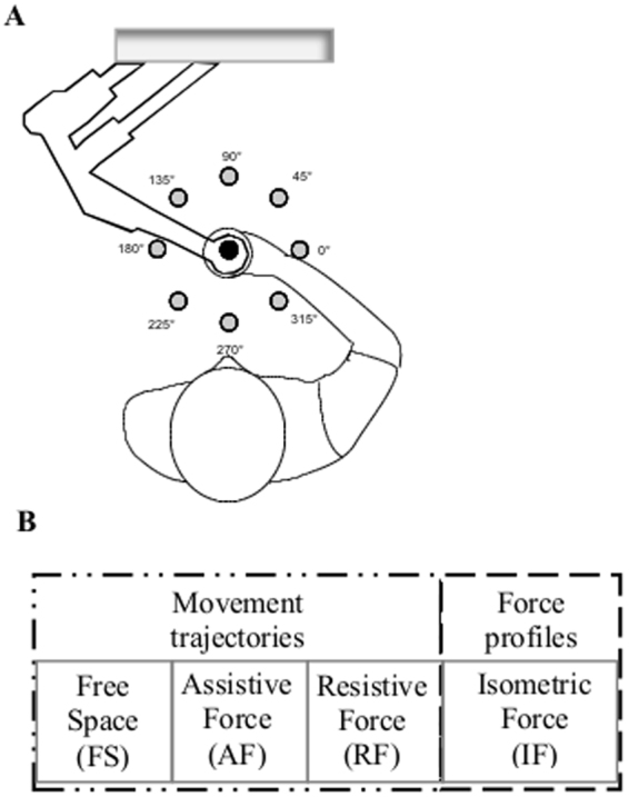
Experimental set-up and protocol. (A) Schematic representation of the experimental setup and targets positions. The circles represent the positions of the peripheral targets on the computer screen; in black is the home target, in grey the eight targets presented during the experimental protocol. (B) Experimental protocol. Tasks in different mechanical environments (from left to right): free space (FS), assistive force (AF), resistive force (RF) and isometric force (IF).