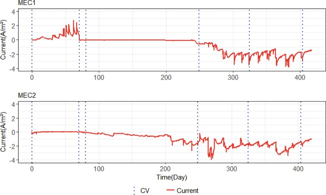
FIG 1.
Current generation with time in MEC1 and MEC2. The positive current in MEC1 represents the current when the anodes were controlled at −0.2 V versus SHE. The negative current in both MECs represents the current when cathodes were controlled at −0.65 V versus SHE. Dashed lines indicate when normal operation was stopped and CV tests were carried out.

