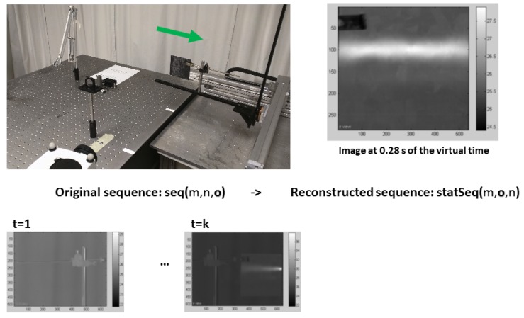
Figure 2.
Pseudo-static sequence reconstruction. At the bottom of the figure, two images from the original sequence at different times are shown. Above these images, the experimental set-up is shown: the IR camera and the inspected sample can be seen as well as the 2-axis electric actuator used to displace the sample. The green arrow indicates the direction of displacement. On the right, an image from the reconstructed pseudo-static sequence is shown. Adapted from [17].

