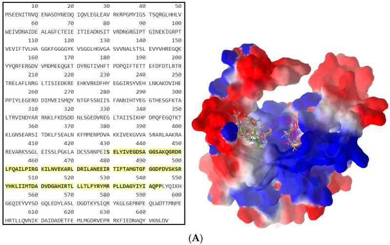
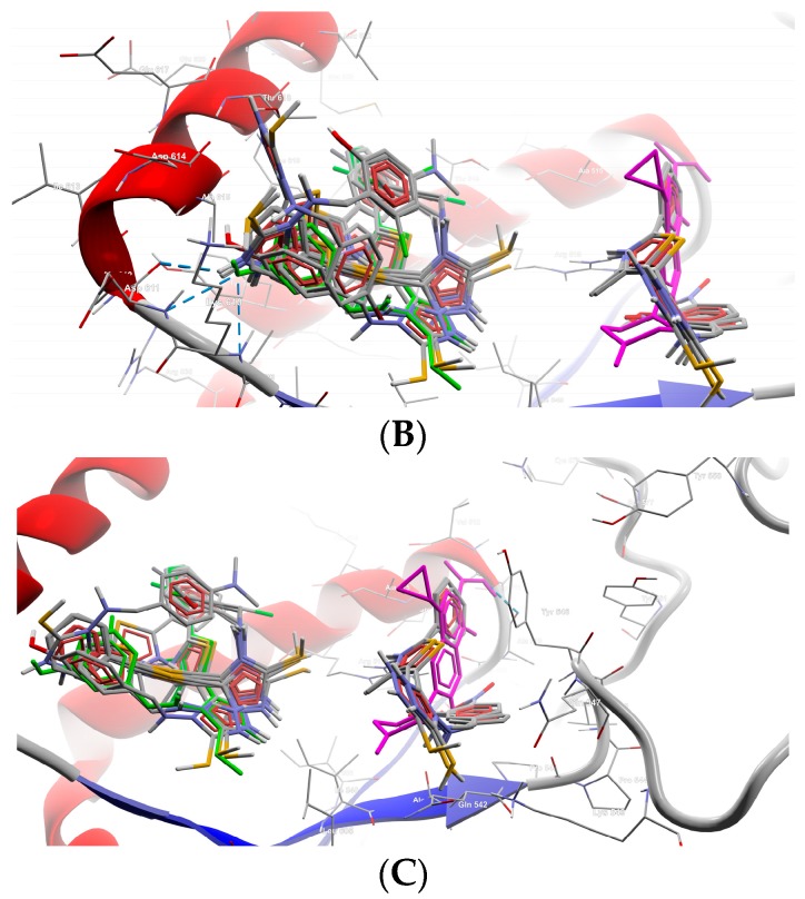
Figure 3.
General view (A) and details (B,C) of the best docking poses of ligands against gyrB. Target is depicted as thin sticks with a secondary structure drawn as a cartoon backbone and semi-transparent electrostatic molecular surface (cropped in the detailed view), where ligands are figured as ball-and-stick (CIP is pink-magenta, B8 is green, meanwhile the rest of the Schiff bases are CPK colored). In the general view (A), the right group is made from CIP, B10, B11, and B13; meanwhile, the left group is made of the rest of the Schiff bases (including here B8); Detail (B) shows the left group (B8 group), image being focused on B8 (green) binding mode, emphasizing the three H-bonds established with Lys610 and Asp611 (2 H-bonds) (cropped view showing only the nearest AAs residues–until a 7.5 Å distance from B8); Detail (C) shows the right group (CIP group), image being focused on the CIP (pink-magenta) binding mode, emphasizing the H-bond established with Ala510 (cropped view showing only the nearest AAs residues–until a 7.5 Å distance from CIP).


