
Fig. 8.
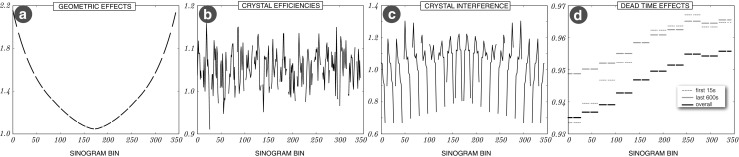
Transaxial sinogram profiles of normalisation factors for four different components: a in-plane geometric effects; b crystal efficiencies—for each sinogram bin the factor is a sum of products of two crystal efficiencies per each LOR contributing to the sinogram bin; c crystal interference (transaxial block effects); d detector dead time for each detector sinogram bin which can be a combination of multiple LORs. For this correction bucket single rates are required and are obtained from list-mode processing (cf. “List-mode Data Processing”). Note that the discontinuities in the plots stem from the dead crystals acting as gaps between detector blocks