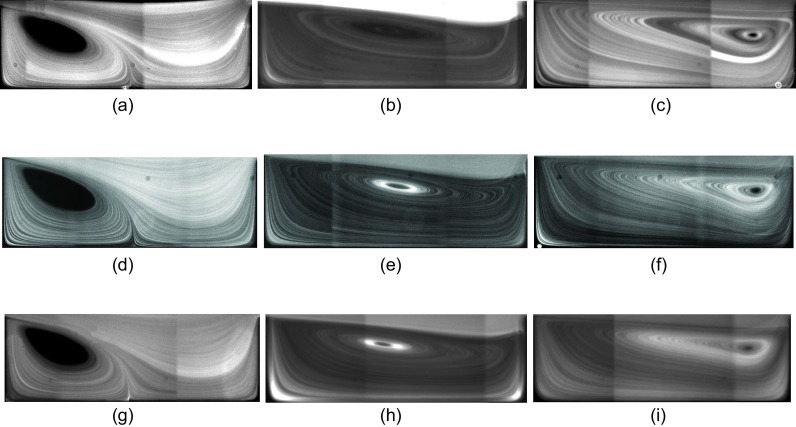
FIG. 4.
Fluorescent imaging of flow inside the L3 cavity connected to channels with m (a)–(c), m (d)–(f), and m (g)–(i) at different Re using m tracers. Considering the difference in hydraulic diameter, the flow rates required to generate a specific Re in a wider channel is larger. Regardless of the difference between Wch, the morphology of vortices is almost similar at identical Re. (a) Wch = 30 μm, Re = 63, (b) Wch = 30 μm, Re = 123, (c) Wch = 30 μm, Re = 216, (d) Wch = 40 μm, Re = 63, (e) Wch = 40 μm, Re = 123, (f) Wch = 40 μm, Re = 216, (g) Wch = 50 μm, Re = 63, (h) Wch = 50 μm, Re = 123, and (i) Wch = 50 μm, Re = 216.

