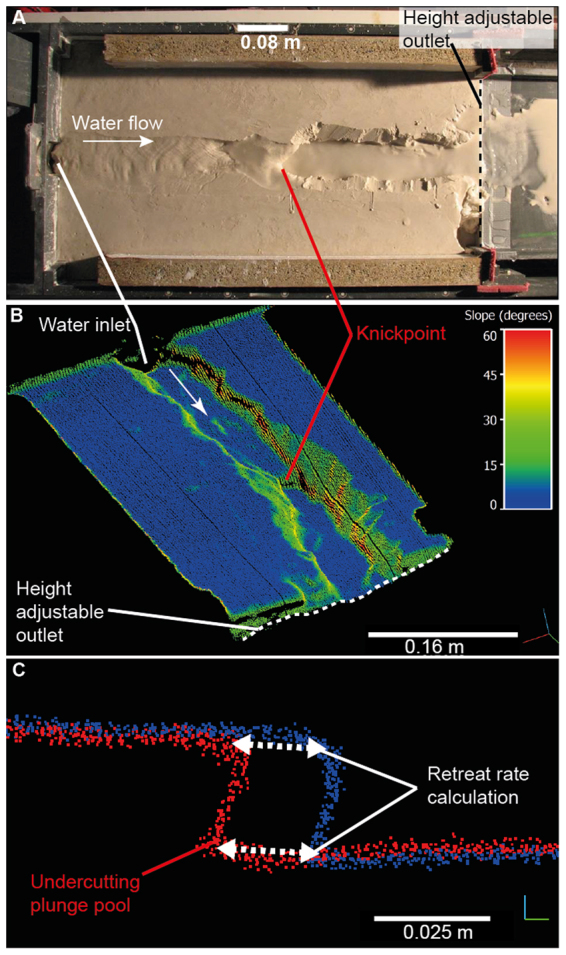
Figure 2.

(A) Photograph of the 0.65 × 0.3 × 0.15 m experimental box flume, with water flowing from left to right and discharge regulated by a pump on the inflow pipe. The channel was perturbed by dropping the height-adjustable outlet to simulate instantaneous base level fall. Over the course of the experiment, the knickpoints retreated upstream (from right to left) in the form of waterfalls (some adjusted their morphology mid-experiment into steepened channel reaches) through the homogenous, cohesive, silica material, and were monitored at regular intervals using a terrestrial laser scanner. (B) Oblique view of an example high resolution point cloud of the channel morphology during an experiment, with colours indicating the local topographic slope. The knickpoint can be seen approximately halfway up the channel, and the white arrow indicates the flow direction. (C) Example of two channel profiles (extracted along the thalweg) showing knickpoints that have developed undercutting plunge pools. The dashed white arrows show the distance between the lip and the base of knickpoints in two scans at different stages of the experiment, used to calculate knickpoint retreat rate.
