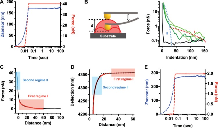
FIG 2 .
Holdfast response to AFM indentation and creep compliance experiments suggests a layered structure. (A) Representative creep compliance curve from a holdfast measured with a constant loading force of 40 nN and a dwell time of 120 s, to probe holdfast core (from 32 curves recorded during 3 independent experiments). In this experiment, the AFM tip indented the holdfast particle until the trigger force was reached (dotted curves). Once the probe reached the set trigger force (40 nN), the particle was kept at a constant force (red curve) for 120 s (solid curves). Particle deformation over time was recorded as changes in z-piezo extension (Z-sensor channel, blue curve). (B) (Left) Schematic illustrating the indentation (δ) of the AFM tip, deforming the holdfast, as described in the main text. (Right) Force-versus-indentation curves for the mica substrate (black curve) and three holdfast particles (each shade of green represents a different particle). Illustrations of regime I (red dotted line) and regime II (blue dotted line) are starkly different with respect to the magnitude and range of force opposing tip advancement. (C) A representative indentation curve (force versus distance) from a control, nontreated holdfast incubated for 16 h on the surface (from 310 curves recorded on 86 holdfasts during 10 independent experiments), showing separate fits to the brush layer model in the first regime (red line) and an effective, linear spring model in the second regime (blue line). (D) Simultaneous fits to brush layer and simple Hertz models in the first and second regimes, with fit parameters given by AFM tip deflection far from the sample. d0 = 4.2 × 10⁻⁹ m; holdfast height (h) = 42.5 × 10⁻⁹ m; holdfast surface (Z0) = 4.357 × 10⁻⁶ m; Young’s modulus of the holdfast core (Ebulk) = 0.348 × 10⁹ Pa; brush layer thickness (L0) = 279 × 10−9 m; brush layer density (Γ) = 0.31 × 10¹⁷ m−2. The fits exclude a transition region at the surface of holdfast where neither a linear elastic model nor a brush layer model strictly hold. (E) Representative creep experiment curve performed on a holdfast brush layer (16 h after deposition on mica) with a constant force of 2 nN and a dwell time of 180 s (from 21 curves recorded during 2 independent experiments). First, the tip indents the holdfast particle until the trigger force is reached (dotted lines). Then, once the probe reaches the set trigger force, the particle is deformed at a constant force for 180 s (solid lines). The particle deformation over time is recorded as changes in the piezo extension Z (Z-sensor channel, blue curve) under a constant loading force (red curve).

