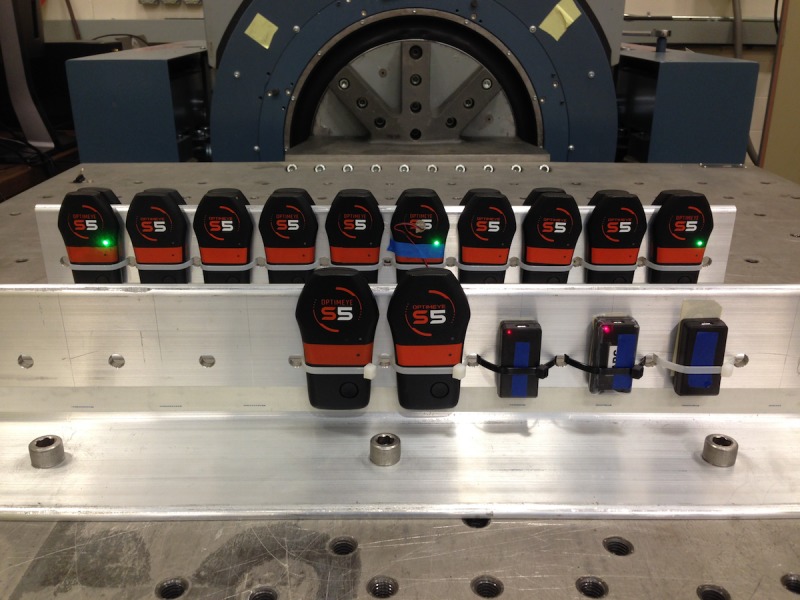
Fig 1. Accelerometer mounting bracket and shaker table configuration.

The shaker table motion is in the fore-aft direction in this photo. As attached, the devices are subjected to motion in the X direction (front-back). The mounting bracket is rotated 90 degrees on the shaker table for Y direction motion (side-side). For Z direction motion, the table is removed, the drive motor is rotated 90 degrees, and the mounting bracket is attached directly to the drive motor output mount.
