Fig. 5.
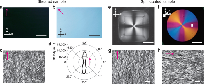
Alignment control by mechanical shearing and spin-coating. a, b Typical POM images and c SEM image of assembly of HAp nanorods oriented by mechanical shearing. d Two-dimensional distribution of the c axes of HAp in the sheared assembly based on XRD. The magenta arrows in (a–d) represent the direction of shearing. e, f Typical POM images obtained (e) without and (f) with a wave plate of the assembly oriented by spin-coating at 2000 rpm on a glass slide. g, h SEM images of spin-coated assemblies obtained at positions denoted by I and II in (f). The magenta arrows in (g, h) show alignment directions. A Analyzer, P Polarizer, Z’ slow axis of the wave plate. Scale bars, a, b 1 mm, c 100 nm, e 1 cm, f 0.5 cm, and g, h 100 nm

