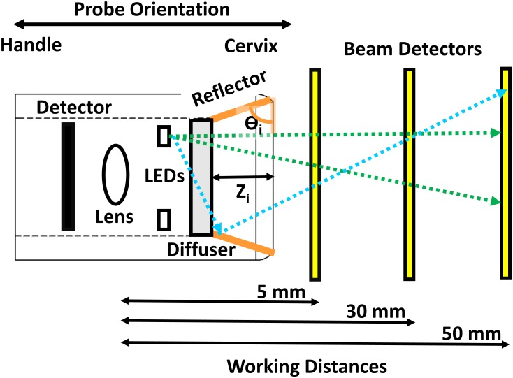
Fig 2. Schematic of reflector optimization ray tracing experiments.
This figure shows the layout of our computer-aided optimization of the angle and height of the reflective surface with the probe tip facing the cervix to the right. The probe (left to right) contains the camera detector, lens, light emitting diode (LED) ring, LED diffuser, and reflector cone (orange). The geometric position and optical illumination properties of our LEDs were taken from manufacturer provided data files. A clear polycarbonate diffuser was modeled and placed over the concentric LED ring. Plate beam detectors were placed in the simulation at working distances from 5, 30, and 50 mm (yellow). These working distances are representative the range of highest, most commonly used, and lowest magnifications of our system. Three- dimensional models of each reflector design were placed in into the ray-tracing simulation. The reflector angles (Ɵi) ranged from 0 to 75° degrees in 15° increments (orange). An outer probe diameter limit of 18 mm limited the range of reflector heights (Zi) from 0–4.82 mm. The effect of the reflector height alone was also investigated, where the reflector angle (Ɵi) was fixed at 90° and the reflector heights (Zi) were varied from 0–4.82 mm.

