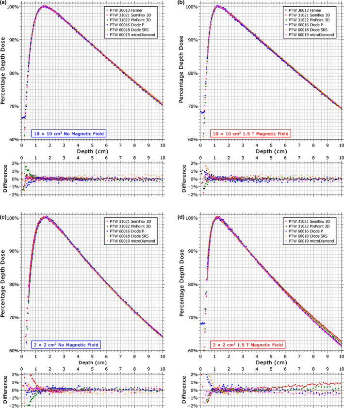
Figure 3.

Percentage depth dose curves measured by each detector with and without a 1.5 T magnetic field for a 10 × 10 cm2 field (a, b) and for a 2 × 2 cm2 field (c, d). The data were normalized to the maximum of a best‐fit curve; represented by the solid lines (RMS error ~0.2%). The differences shown are with respect to the mean value at each point and are relative to the maximum dose. [Color figure can be viewed at wileyonlinelibrary.com]
