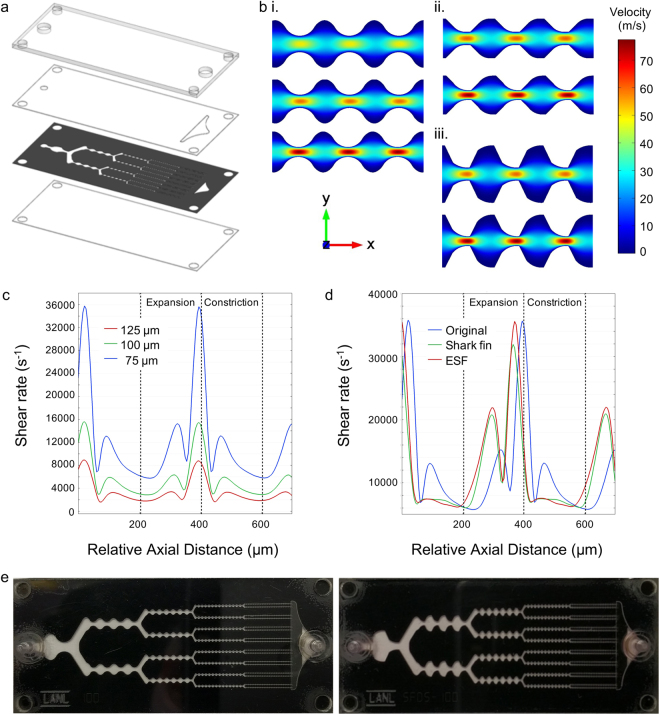
Figure 1.
Single layer, polyimide based microfluidic device with new channel designs. (a) Exploded view showing the four device layers including, from top to bottom, acrylic top layer, PET outlet layer, channel layer produced by laser-etching polyimide film, and PET bottom layer. Adhesive transfer tapes were laminated to the PET layers and used to hold the device together. Holes used to attach hose barbs are shown in the top layer. (b) Finite-element fluid dynamics simulations showing velocity profiles for the (i) original, (ii) shark fin, and (iii) extended shark fin designs at (top to bottom) 125, 100, and 75 μm minimum widths. Simulations were performed at 1 mL/min. Decreasing channel width led to higher maximum flow velocities in the channel constrictions, while the extended shark fin provided greater variation in flow rate between the expansions and constrictions. (c) Shear rate at the device centerline for the original design at different channel widths. Three shear rate peaks can be seen, all of which increase as width becomes smaller. The major peak corresponds to fluid acceleration between the expansions and constrictions, and the two smaller peaks are due to fluid deceleration within the separate regions. (d) The shark fin and ESF designs enhance shear rate due to fluid deceleration within expansions, but there is no longer a second peak within constrictions. (e) Pictures of fabricated single layer devices with (left) original and (right) extended shark fin designs. Both devices had a minimum channel width of 100 µm in the fifth stage.

