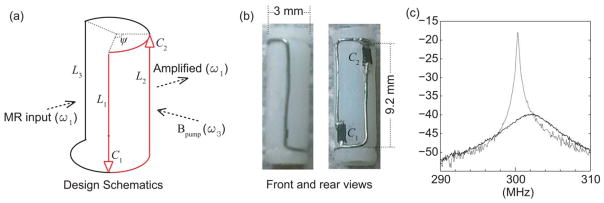
FIG. 1.
The schematic diagram (a) and the pictures (b) of a cylindrically shaped WAND. The detector is made of a 32-gauge metal wire mounted on a 3-mm-diameter cylinder over a 9.2-mm length. The metal wire is self-connected by two varactor diodes (C1 and C2) bridging across the gaps. The two leg inductors (L1 and L2) are symmetrically distributed with respect to L3. The rectangular loop containing the two varactors creates the high-frequency resonance mode, whereas the low-frequency mode generates a magnetic field that is parallel to this rectangular loop. The span angle, ψ, between L1 and L2 can be empirically adjusted around 90° to make the higher-resonance frequency approximately twice the lower-resonance frequency. (c) S21 curve measured with a double pick-up loop placed above the resonator and connected to a network analyzer. The solid curve is measured in the absence of pumping power, and the dotted curve is measured in the presence of pumping power that is approximately 0.4 dB below the resonator’s oscillation threshold.

